Power factor is often expressed as leading power factor or lagging power factor pf. It is always measured between 0 and 1 and is best determined by the leading or lagging current with regard to voltage. The terms ‘leading’ and ‘lagging’ describes where the load current phasor lies in relation to the supply voltage phasor. Leading or lagging are calculated by the sign of the phase angle between the current and voltage waveforms. Capacitive resistive loads will, therefore, cause a leading power factor, whereas an inductive load will cause a lagging power factor.
To understand power factor, we’ll first start with the definition of some basic terms:
KW is Working Power (also called Actual Power or Active Power or Real Power). It is the power that actually powers the equipment and performs useful work.
KVAR is Reactive Power. It is the power that magnetic equipment (transformer, motor and relay) needs to produce the magnetizing flux.
KVA is Apparent Power. It is the “vectorial summation” of KVAR and KW.
Power factor is the ratio of useful power to perform real work (active power) to the power supplied.
Equation 1.
In other words, the power factor ratio measures the percentage of power expended for its intended use in ac circuits. Power factor ranges from zero to unity. A load with power factor of 0.9 lagging denotes that the load can effectively expend 90% of the apparent power supplied (VA) and power correct it to perform useful work (W). The term "lagging power factor" denotes that the fundamental current lags behind the fundamental voltage by 25.84°.
In the sinusoidal case there is only one phase angle between the voltage and the current (since only the fundamental frequency is present), the power factor can be computed as the cosine of the phase angle and is commonly referred to as the displacement power factor,
In addition to the electrical power consumed by equipment like heating, lighting, and electric motors in a distribution system, (which is known as "real" or "active" power), an electrical system may also draw inductive current phase which is not directly used due to the magnetic fields. This is known as "reactive power". The combination of two is known as called "apparent power". PF is the relationship between real power and the apparent power (kVA).
If your site has a poor power factor, you could be paying for energy that cannot be used. Electric utilities alway want their customers to have high power factor.
Equation 2
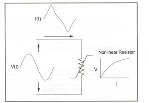
In the nonsinusoidal case the power factor cannot be defined as the cosine of the phase angle as in Equation 2. The PF that takes into account contribution from all active power both fundamental and harmonic frequencies is known as the true PF. The true power factor is simply the ratio of total active power for all frequencies to the apparent power delivered by the utility as shown in Equation 1.
Power quality monitoring instruments now commonly report both correcting and true power factors. Many devices such as switch-mode power supplies and PWM variable speed drives have a near-unity displacement power factor and are considered power factor corrected, but the true power factor may be 0.5 to 0.6. An ac-side capacitor will do little to improve the true power factor in this case because Q1 is zero. In fact, if it results in resonance, the distortion may increase, causing the power factor to degrade. The true PF indicates how large the power delivery system must be built to supply a given load. In this example, using only the displacement PF would give a false sense of security that all is well.
The bottom line is that distortion results in additional current components flowing in the system that do not yield any net energy except that they cause losses in the power system elements they pass through. This requires the system to be built to a slightly larger capacity to reduce power to the load than if no distortion were present.
Here is a typical power triangle.
Relationship of the components of Apparent Power.

This 100+ page e-book is a great guide for those who have a basic interest in the field of electricity. This well-illustrated e-book, coupled with some basic knowledge of electricity, will give you a broad theoretical background in this fundamental subject.
CONTENTS