Fault Current Calculation Explained
By William Conklin, Associate Editor
By William Conklin, Associate Editor
Our customized live online or in‑person group training can be delivered to your staff at your location.

Fault current calculation determines the maximum current that can flow during a short-circuit condition and whether protective devices will interrupt it without failure. In electrical protection engineering, this value marks the boundary between controlled fault clearing and equipment damage.
Designers rely on calculated fault current values to confirm that circuit breakers, fuses, relays, bus structures, and switchgear can withstand worst-case electrical stress. When the calculated value is too low, protective devices may fail mechanically or thermally during a fault. When overly conservative, systems become oversized, costly, and difficult to coordinate. In either case, reliability suffers.
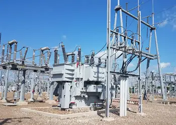
For this reason, fault current calculation is not an academic exercise. It is a core input to short-circuit studies, coordination analysis, equipment rating verification, and compliance documentation. Every electrical system, from a commercial service entrance to a utility substation, depends on fault-current modeling that reflects real system conditions.
The calculated result is ultimately documented as available fault current at specific locations so inspectors, engineers, and equipment suppliers can verify that interrupting and withstand ratings remain adequate as systems evolve.
This article explains how fault current is calculated, which inputs and assumptions determine the result, how different fault conditions affect its magnitude, and why the modeling discipline is central to modern protection design.
Fault current calculation defines the maximum electrical stress that protection equipment must withstand during abnormal conditions. It determines whether breakers, fuses, and relays can interrupt fault currents within their rated limits before damage propagates through the system.
These calculations are performed as part of short-circuit studies and then applied to coordination analysis, equipment selection, and rating verification. The goal is not simply to produce a number, but to confirm that the protection system can survive its most severe operating condition without cascading failure.
Stay informed with our FREE Electrical Protection Newsletter — get the latest news, breakthrough technologies, and expert insights, delivered straight to your inbox.
Within the broader discipline of electrical protection, fault current calculation anchors every downstream decision. If the modeled values do not reflect actual system behavior, coordination studies, labeling, and equipment ratings lose meaning.
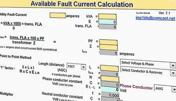
Fault current calculation involves determining the prospective short-circuit current at defined points in the system under specified conditions. This requires more than a formula. It requires accurate system modeling and sound engineering judgment.
Key inputs include source strength, transformer ratings and impedance, conductor characteristics, system configuration, and grounding method. Each of these elements influences total system impedance and, therefore, the magnitude of current that can flow during a fault.
Assumptions matter. Utility contribution may vary over time. Transformer impedance tolerances affect worst-case results. Conductor length, parallel paths, and connection changes alter impedance in ways that are often overlooked after initial design. Software tools assist with these calculations, but the output is only as reliable as the data and assumptions behind the model.
This is where fault current calculation differs from basic electrical theory. The task is not to demonstrate Ohm’s Law, but to model a system as it actually exists and as it may exist after future modifications.
At a conceptual level, fault current increases as system impedance decreases. Voltage establishes the driving force, but impedance governs the result.
While simplified expressions such as I = V ÷ Z illustrate the relationship, real systems include resistance, reactance, and transient effects that influence both magnitude and peak current. In three-phase systems, transformer-based calculations are commonly used to estimate prospective short-circuit current at the secondary terminals, based on transformer kVA, operating voltage, and percent impedance.
These calculations provide a baseline, but they do not eliminate the need for worst-case evaluation.
Maximum fault current calculation defines the highest prospective short-circuit current that can occur at a given location under the most severe credible conditions. This value governs interrupting ratings, momentary withstand limits, and mechanical stress on conductors and bus structures.
Engineers evaluate this condition by assuming minimum system impedance, full upstream source contribution, and transformer impedance values that favor maximum current flow. The result represents the electrical stress that the electrical stress protection equipment must withstand during the first cycles of a bolted fault.
Underestimating maximum fault current can lead to catastrophic device failure. Overestimating it can result in excessive equipment cost without a corresponding safety benefit. Accurate modeling, therefore, controls both reliability and design efficiency.
Maximum fault current is not a separate discipline. It is the limiting case in fault current calculation that determines whether the protection system survives its most extreme operating condition.
Fault current is not constant during a short circuit. Symmetrical current represents the steady-state sinusoidal component after transient effects decay. Asymmetrical current includes the initial DC offset that produces higher peak currents during the first few cycles.
This distinction matters when specifying breakers and relays that must withstand both peak mechanical forces and steady-state thermal stress. Fault current calculation must account for both conditions to ensure proper equipment application.
Fault current magnitude varies with fault type and system grounding:
Line-to-ground faults are the most common but may produce lower current depending on the grounding method.
Line-to-line and double line-to-ground faults typically produce higher currents.
Three-phase faults generate the highest short-circuit levels and are used to evaluate maximum fault conditions.

Protection systems rely on coordination between relays and circuit breakers to isolate these faults without unnecessary upstream outages.
Short-circuit studies support more than interrupting rating verification. They perform voltage depression analysis, mechanical stress evaluation of conductors and busbars, and system reliability assessment by identifying weak points under fault conditions.
Fault current data also supports transformer protection by confirming that windings and insulation remain within acceptable limits during fault events. These results directly influence overcurrent protection strategies and relay applications.
Modern fault current analysis relies on software to model complex systems and efficiently evaluate multiple fault scenarios. The purpose of standards in this context is not compliance for its own sake, but consistency.
Calculation frameworks establish common modeling assumptions, define acceptable methods, and ensure that results are comparable across studies and projects. When fault current calculations follow disciplined modeling practices, protection decisions remain defensible as systems expand and change.
Fault current values are also essential when specifying equipment such as metal-clad switchgear, where mechanical withstand ratings must align with calculated fault stresses.
Explore 50+ live, expert-led electrical training courses –