Wire and Cable
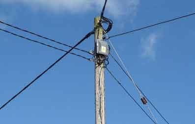
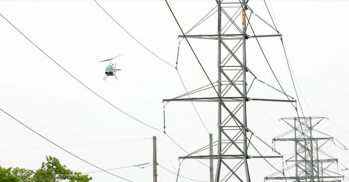
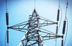
Aerial Cable Explained
Download Our FREE Wire and Cable Handbook
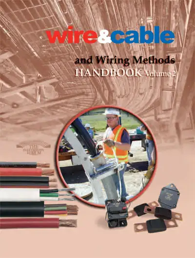
Wire & Cable Handbook Vol. 2
This 100+ page handbook discusses wire and cable installation, testing and maintenance as well as many aspects to proper and effective proactive, predictive electrical maintenance and overall proper power wire and cable management systems.
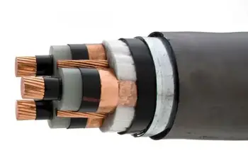
In Volume 2, we dive deeper into the complexities of wire and cable systems, addressing topics such as insulation types, conductor materials, cable construction, and performance standards. We also explore the latest innovations in cable technology, including high-performance and specialty cables designed to meet the demands of evolving industries such as renewable energy, telecommunications, and automation. With a focus on real-world applications, this handbook offers practical insights into selecting the right cables for specific environments, troubleshooting common issues, and adhering to safety and regulatory standards.
Designed to be both a practical guide and a comprehensive reference, Volume 2 of the Wire & Cable Handbook is ideal for professionals involved in the design, installation, and maintenance of electrical systems. Whether you're working with low-voltage, medium-voltage, or high-voltage cables, this volume equips you with the knowledge and tools needed to make informed decisions, optimize system performance, and ensure the safety and longevity of wiring and cabling networks.
With an emphasis on current industry trends and best practices, this volume is a valuable resource for anyone seeking to stay ahead of the curve in the ever-evolving field of electrical wiring and cabling.
Latest Wire and Cable Articles
Power Cable Diagnostics - Field Applications and Case Studies
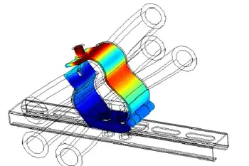
Cable Cleats Testing - Crucial to Cable Management
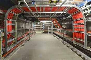
Guidelines for the Installation of Cable In Cable Trays

Copper Wire Theft
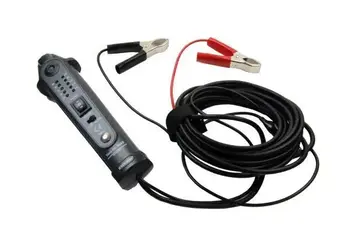
Testing of Electrical Power Cable

Copper Underground Electrical Transmission Systems
Wire and Cable Media


Wire and Cable Articles From ET Magazine
FERC Complaint Targets Duke, PJM Transmission Planning

FERC Approves Interconnection for Talen Energy, Amazon Data Center
FirstEnergy Explores Alternatives to PJM Capacity Market
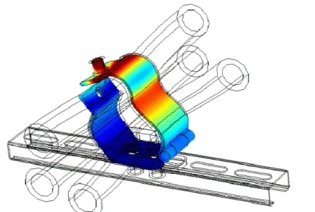
Cable Cleats Testing - Crucial to Cable Management
Sign Up for Electricity Forum’s Wire and Cable Newsletter
Stay informed with our FREE Wire and Cable Newsletter — get the latest news, breakthrough technologies, and expert insights, delivered straight to your inbox.
Electricity Today T&D Magazine Subscribe for FREE

- Timely insights from industry experts
- Practical solutions T&D engineers
- Free access to every issue