Utility Transformers
OLTC Transformer Explained
Download Our FREE Utility Transformers Handbook
Electrical Transformer Testing Handbook, Vol. 5
The proper maintenance of transformers is crucial to not only keeping operations running, but running at peak efficiency.
In this edition, we cover a wide range of transformer testing methods, from routine tests to advanced diagnostic procedures, including insulation resistance, turns ratio, winding resistance, and load testing. We also examine the latest innovations in transformer testing technologies, such as online monitoring systems and condition-based assessment techniques that enable early fault detection and proactive maintenance. These advancements are essential for enhancing operational efficiency and reducing downtime, making transformer testing more predictive and less reliant on reactive repairs.
With practical insights and step-by-step guidance, Volume 5 serves as an essential resource for engineers, maintenance professionals, and technicians involved in transformer testing and condition monitoring. This volume offers detailed instructions for conducting accurate tests, interpreting results, and troubleshooting common issues. It also explores the impact of environmental factors, operational stresses, and aging on transformer performance, helping professionals identify potential risks and take preventative measures.
Latest Utility Transformers Articles
The Distribution Transformer and Grid Reliability
How Many Volts Go Into a Distributor Bucket Transformer
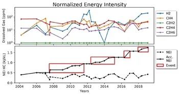
Dissolved Gas Analysis Advancements Explained
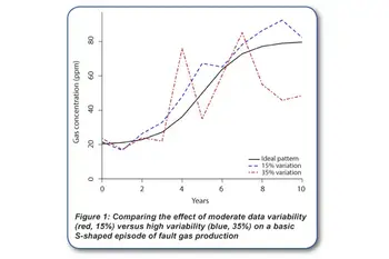
Advancements in DGA Data Quality
Transformer Nameplate Explained
Transformer Oil Explained
Utility Transformers News
Utility Transformers Media

Utility Transformers Articles From ET Magazine

The Role of Transformer Oil Alternatives in Improving Safety and Environmental Sustainability

Enhancing Transformer Resilience: Fire Barriers and Safety Measures in Modern Substations

Navigating the Transformer Supply Crunch: Strategies for Utilities Amidst Global Shortages

MITIGATING TRANSFORMER FAILURES: ADVANCED MONITORING AND MAINTENANCE STRATEGIES
Sign Up for Electricity Forum’s Utility Transformers Newsletter
Stay informed with our FREE Utility Transformers Newsletter — get the latest news, breakthrough technologies, and expert insights, delivered straight to your inbox.
Electricity Today T&D Magazine Subscribe for FREE

- Timely insights from industry experts
- Practical solutions T&D engineers
- Free access to every issue