Dielectric Fluid Performance in HV Equipment
By Frank Baker, Technical Editor
By Frank Baker, Technical Editor
Our customized live online or in‑person group training can be delivered to your staff at your location.

Dielectric fluid governs how electrical insulation and heat dissipation behave under load and fault stress. When its condition degrades, transformer cooling margins shrink, insulation aging accelerates, and failures develop long before external measurements indicate risk.
In practice, dielectric fluid determines far more than whether insulation survives a laboratory test. It shapes transformer loading limits, cooling effectiveness, aging rates, and the way faults emerge when electrical stress concentrates unevenly inside the insulation system. Long before alarms trip or temperatures rise, changes in fluid behavior can quietly redefine how the system responds to stress.
In transformer and capacitor applications, dielectric fluid serves as both an insulating medium and a heat-transfer path. It influences how electric fields distribute across solid insulation and how thermal energy is removed from energized components. When fluid properties drift, electrical stress becomes localized, partial discharge activity increases, and insulation life shortens even though nameplate conditions still appear normal.
This article examines how insulating fluids behave inside real equipment, how different fluid families influence electrical and thermal performance, how material compatibility affects insulation life, and how diagnostic testing is used to interpret fluid condition before degradation becomes irreversible.
Inside energized equipment, dielectric fluid performs two simultaneous roles that cannot be separated. It provides electrical insulation by suppressing the concentration of the electric field between conductors, and it removes heat generated by current flow, core losses, and harmonic effects. If either role weakens, the other quickly follows. An oil-filled transformer relies on this fluid to provide both insulation and cooling, ensuring safe and efficient operation.
Download our FREE Electrical Training Catalog and explore a full range of expert-led electrical training courses.

In transformers and capacitors, the fluid fills microscopic voids that would otherwise become partial-discharge sites. At the same time, it transports thermal energy toward tank walls, radiators, or cooling systems. The result is not just lower temperature, but more uniform electrical stress across insulation surfaces. Uniform stress is what preserves dielectric strength over time. Core parts of transformer components are submerged in fluid to minimize electrical discharge and control temperature.
This dual function explains why fluid condition often predicts failure earlier than winding resistance or temperature readings. When dielectric properties begin to drift, insulation aging accelerates even if external measurements still appear acceptable.
High-voltage transformers remain the dominant application, but dielectric fluids are equally important in capacitors, bushings, tap changers, and certain cable systems. Each environment stresses the fluid differently.
Transformers demand oxidation resistance and moisture control. Capacitors demand stable dielectric behavior under rapidly changing electric fields. Bushings demand chemical compatibility with layered insulation systems. These performance differences are reflected during a power transformers health check, where fluid behavior often reveals early reliability risks.
In utility and industrial settings, failures rarely originate from a single dramatic fault. They more often develop from slow chemical or moisture-driven degradation that quietly weakens insulation until a switching event or overload exposes the damage. Proper transformer insulation depends on the fluid’s ability to prevent arcing and maintain thermal stability under load.
Dielectric fluids have also become central to immersion cooling in data centers and high-power electronics. Instead of relying on air movement, components are submerged directly in thermally stable insulating liquids that remove heat far more efficiently.
What makes this approach effective is not only improved heat transfer, but also electrical safety. The fluid allows direct contact with energized surfaces without short circuits, enabling compact layouts and higher power densities. Many of the same thermal control principles used in immersion systems are derived from traditional transformer cooling practices.
However, immersion cooling places even greater importance on fluid purity, chemical stability, and material compatibility. Small contamination levels that might be tolerable in a transformer can become significant in electronic environments. Regular testing of transformer oil filling is essential to avoid contamination and maintain high dielectric strength.
Mineral oil remains widely used because of cost and familiarity, but its limitations are well understood. Lower fire points, poor biodegradability, and moisture sensitivity have driven the adoption of ester-based alternatives.
Natural esters offer high fire points and excellent moisture tolerance, making them attractive for indoor or environmentally sensitive installations. Synthetic esters extend thermal stability and oxidation resistance, supporting higher operating temperatures and longer service life. Emerging nanofluids promise further gains in heat transfer and dielectric strength, although their long-term behavior is still being evaluated. Monitoring breakdown voltage helps evaluate the condition of the fluid and ensures they can withstand high voltages.
The shift away from mineral oil is not driven by marketing trends. It is driven by decades of service data showing that fire risk, moisture behavior, and aging performance ultimately determine lifecycle cost more than purchase price. These differences are summarized in greater detail within the characteristics of dielectric fluid performance classifications.
| Fluid Type | Key Properties | Advantages | Limitations |
|---|---|---|---|
| Mineral Oil | Moderate dielectric strength, good cooling, low cost | Widely available, proven track record | Low fire point, poor biodegradability |
| Natural Ester | High dielectric strength, high fire point (>300°C) | Biodegradable, excellent moisture tolerance | Higher cost, potential oxidation if unmanaged |
| Synthetic Ester | High thermal stability, excellent oxidation resistance | Long service life, superior high-temperature performance | Expensive, less eco-friendly than natural esters |
| Nanofluids | Enhanced dielectric strength and heat transfer via nanoparticles | Improved cooling, reduced aging, and emerging technology | Still experimental, higher production cost |
Fluid selection is rarely a single-property decision. Engineers balance fire safety, environmental exposure, thermal limits, oxidation resistance, viscosity, and maintenance strategy.
Think you know Utility Transformers? Take our quick, interactive quiz and test your knowledge in minutes.
A natural ester may offer superior fire safety but require careful oxidation management. A synthetic ester may tolerate higher temperatures but carry a higher material cost. Nanofluids may offer performance benefits while introducing new compatibility questions. Each choice reflects the facility's operating philosophy as much as its technical specifications.
Good selection aligns the fluid with the equipment’s thermal profile, loading behavior, and expected service life rather than simply matching nameplate ratings.
Dielectric fluids interact continuously with solid insulation, gaskets, and seals. Compatibility problems rarely appear immediately. They develop slowly as swelling, softening, or chemical degradation that eventually compromises sealing or insulation strength.
Cellulose insulation depends on proper impregnation to maintain dielectric strength. When fluid penetration is incomplete or moisture remains trapped, partial discharge activity increases, and insulation life shortens. Vacuum-pressure impregnation is used not for convenience, but because it removes the conditions that lead to early failure.
Even fluid temperature during impregnation matters. Slight heating improves flow and penetration, while excessive heating accelerates oxidation. These details rarely appear in simplified specifications, yet they determine long-term performance.
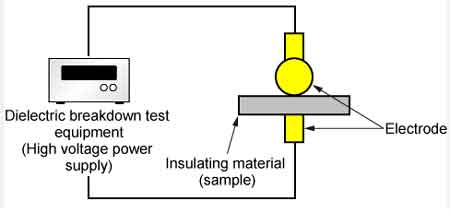
Fluid condition is monitored through breakdown voltage, moisture content, acidity, dissipation factor, viscosity, and dissolved gas analysis. Each measurement reveals a different aspect of fluid health.
Breakdown voltage reflects contamination and moisture. Acidity reflects oxidation. Gas composition reflects thermal or electrical stress inside the equipment. These results are interpreted alongside transformer oil analysis practices described in transformer oil analysis.
Gas behavior is evaluated in greater detail through dissolved gas analysis, which allows engineers to distinguish between thermal, electrical, and discharge-related fault mechanisms.
What makes fluid diagnostics valuable is not the test itself, but the decisions it enables. Early correction prevents insulation damage that no oil treatment can later reverse.
Nanofluids introduce particles that enhance thermal conductivity and dielectric behavior. While still emerging, they demonstrate how fluid technology continues to evolve beyond traditional oil chemistry.
At the same time, sustainability pressures continue to reshape fluid selection. Biodegradability, fire performance, and lifecycle emissions now influence purchasing decisions alongside electrical performance. In many installations, environmental risk is no longer secondary to reliability. The two must coexist.
Selecting dielectric fluid is ultimately a system-level decision. Fire safety requirements may dominate in one installation. Environmental regulations may dominate in another. Maintenance philosophy, spare fluid availability, and transformer design all influence the final choice.
What remains constant is this: insulating fluid is not a passive fill material. It is an active electrical and thermal component of the system. When it is selected, maintained, and monitored with that perspective, equipment life extends and failure risk declines. When it is treated as a background commodity, the system eventually exposes the oversight.
Explore 50+ live, expert-led electrical training courses –