Industrial Electrical Power
Power System Engineering
Power system engineering involves the design, operation, and maintenance of electrical power systems. It ensures efficient energy generation, transmission, and distribution while improving grid reliability and integrating renewable sources across industrial and utility networks.
How Power System Engineering Works
Power System Analysis and Design Course
Arc Flash Analysis/Study Training Course
Power System Fundamentals Course
Short Circuit Analysis/Study Course
The Role of Power Engineers in Modern Energy Networks
Power system engineering plays a pivotal role in designing, optimizing, and maintaining modern electrical networks for industrial, commercial, and institutional electrical systems. As the world transitions to a more sustainable energy…
View more
Test Your Knowledge About Software and Apps!
Think you know Software and Apps? Take our quick, interactive quiz and test your knowledge in minutes.
- Instantly see your results and score
- Identify strengths and areas for improvement
- Challenge yourself on real-world electrical topics
Latest IEP Content
Arc Flash Hazard Explained
Arc flash hazard involves explosive energy from faults in switchgear and panels; NFPA 70E mandates risk assessment, PPE, incident energy analysis, labeling, and OSHA-compliant electrical safety programs to mitigate burns and arc blast.
Why Understanding Arc Flash Hazard Is Important
Arc flash hazard, as defined by the National Fire Protection Association (NFPA), is "a dangerous condition associated with the release of energy caused by an electric arc.” For foundational context on definitions and mechanisms, review what an arc flash is to align terminology across teams.
NFPA 70E Arc Flash Training
CSA Z462 Arc Flash Training
Request a Free Training Quotation
An…
View more
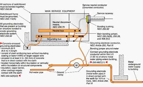
NEC 250.122 Explained
NEC 250.122 defines how to size the equipment grounding conductor (EGC) in an electrical circuit. The rule links the minimum size of the grounding conductor directly to the rating of the overcurrent protective device protecting the circuit, such as a circuit breaker or fuse. Using Table 250.122, electricians determine the minimum copper or aluminum grounding conductor required to safely carry fault current and allow the protective device to clear the fault quickly.
The equipment grounding conductor is not designed to carry normal load current. Its purpose is to provide a low-impedance return path during a ground fault, allowing sufficient current…
View more
Isolation Transformer For Fault and Noise Reduction
An isolation transformer separates electrical systems, altering how faults behave, how noise propagates, and how engineers interpret what they see downstream. Its value is not simply that it “isolates” voltage, but that it establishes a boundary where assumptions about grounding, current paths, and interference no longer hold in the usual way.
In practice, an isolation transformer is introduced when conventional distribution behavior becomes a liability, when sensitive loads misbehave, when measurements become unreliable, or when protection decisions depend on controlling how disturbances propagate through a system. The transformer itself does not eliminate problems. It reshapes them. That distinction matters far…
View more
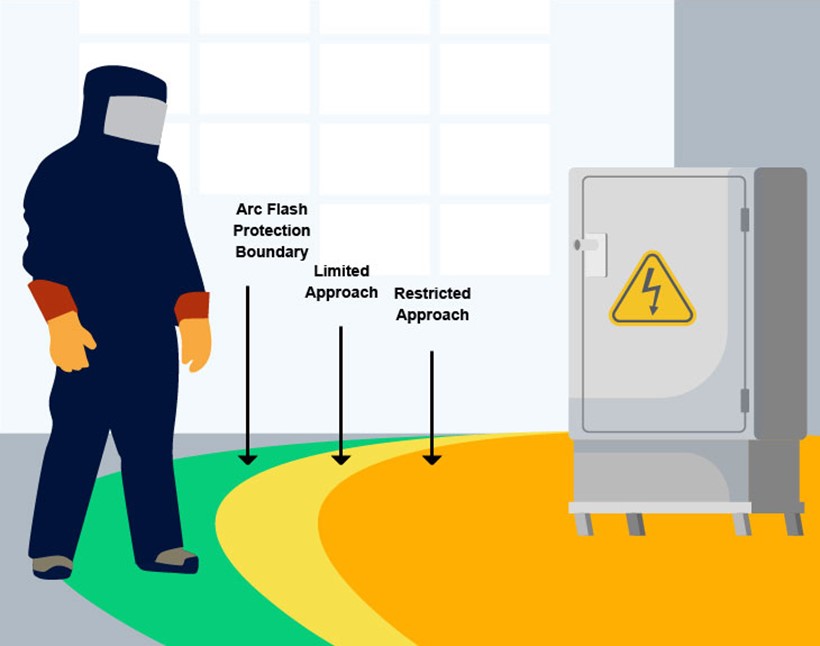
Restricted Approach Boundary
The restricted approach boundary is a shock protection limit defined by NFPA 70E. It marks the distance near exposed energized conductors where only qualified personnel using proper PPE and tools may enter. This boundary helps prevent electrical shock and arc flash injuries.
Understanding the Restricted Approach Boundary for Compliance with NFPA 70E
Understanding the Clearance Zone for Energized Equipment
The restricted approach boundary is part of the NFPA 70E and CSA Z462 framework for managing electrical hazards. This boundary is established at a distance where the risk of electric shock from energized electrical conductors is significantly increased due to…
View more

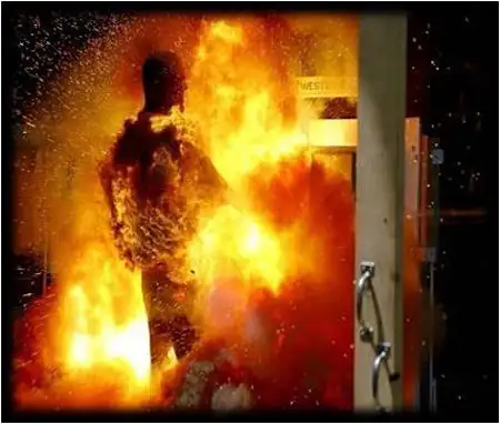
Arc Flash Burn Photos - Don't Let This Be You
Arc flash burn photos illustrate electrical safety hazards, incident energy effects, and injury mechanisms, supporting NFPA 70E compliance, PPE selection, risk assessment, and lockout-tagout training for engineers, electricians, and safety managers.
Arc Flash Burn Photos Explained: What You Need to Know
Arc flash burn photos graphically illustrate the severe injuries that can result from arc flash incidents, highlighting the critical importance of safety protocols in the electrical industry. These photos are intended to show the devastating effects of arc flash burns on the human body, offering a sobering reminder of the potential consequences when safety measures are neglected. Electrical…
View more
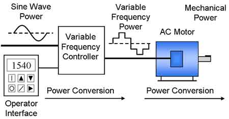
VFD Variable Frequency Drive
A VFD Variable Frequency Drive controls AC motor speed and torque by adjusting voltage and frequency. They improve motor efficiency, ensure drive performance, and reduce energy consumption in industrial, commercial, and HVAC applications.
Understanding How VFD (Variable Frequency Drive) Works
A modern AC drive, also known as an adjustable frequency drive or variable speed drive, allows operators to control the speed of motors by varying the frequency and voltage supplied to the motor windings. At the core of a frequency drive VFD are power electronics such as the insulated gate bipolar transistor (IGBT), which switch rapidly using pulse width…
View more

Electrical Troubleshooting: Step-by-Step
Electrical troubleshooting is the process of diagnosing and fixing problems in power systems, circuits, or components. It involves testing, identifying faults, and restoring safe, reliable operation in residential, commercial, or industrial settings using specialized tools and expertise.
The Complete Guide to Electrical Troubleshooting
Visit Our Electrical Troubleshooting Training Course
It is a crucial skill for diagnosing and resolving energy issues in various systems. Whether it involves a tripped circuit breaker, faulty wiring, or malfunctioning equipment, this process saves time, enhances safety, and prevents further damage to power systems. Workers must be proficient in identifying and solving power faults, which…
View more
IEP News
IEP Media


IEP Articles From ET Magazine

Compatibility Issues with Generator-Backed Power Systems
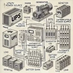
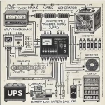
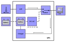
Line-interactive uninterruptible power supply (UPS) systems play a vital role in maintaining seamless operation during power outages. Their integration with backup generators, however, can pose challenges regarding synchronization and power quality.
While both UPS systems and generators serve as safeguards against power disruptions, their integration isn't always seamless. Understanding these compatibility concerns is crucial for ensuring reliable backup power and avoiding damage to sensitive equipment.
Visit Our UPS Systems Study Course
Voltage and Frequency Stability
Generators, particularly smaller portable models, may not provide the same level of voltage and frequency stability as utility power. Line-interactive UPS units are designed…
View more
Line-Interactive UPS in Scalable IT Infrastructure
In the evolving landscape of IT infrastructure, reliable and flexible power solutions are paramount. Scalable line-interactive Uninterruptible Power Supply (UPS) systems provide an essential service to growing IT networks by adapting to increasing power demands without the need for complete system overhauls. This adaptability ensures that businesses can expand their IT capabilities while maintaining protection against power interruptions and fluctuations.
Visit Our UPS Systems Study Course
Scalability and Its Importance
Scalability in a UPS context refers to the ability to increase the UPS capacity to handle higher loads as demand grows. This is particularly crucial for businesses experiencing rapid…
View more
Securing Critical Infrastructure: The Role of Line-Interactive UPS
UPS (uninterruptible power supply) systems are essential for protecting critical infrastructure in healthcare and finance. They provide backup power in the event of a power outage, ensuring that sensitive equipment and data are protected. Line-interactive UPS systems are a popular choice for these applications, offering a number of advantages over other types of UPS systems.
Visit Our UPS Systems Study Course
Benefits of Line-Interactive UPS Systems
Line-interactive UPS systems offer a number of benefits over other types of UPS systems, including:
Lower cost: Line-interactive UPS systems are typically less expensive than other types of UPS systems, making them a…
View more
Battery Advancements and the Impact on Line-Interactive UPS
Advancements in Battery Technology and Their Impact on Line-Interactive UPS
Line-interactive uninterruptible power supply (UPS) systems play a crucial role in ensuring power continuity for sensitive electronic equipment. Serving as a safeguard against power disruptions, these systems seamlessly switch to battery backup during outages, preventing data loss, equipment damage, and downtime. Recent advancements in battery technology, particularly lithium-ion batteries, have significantly influenced the capabilities and performance of line-interactive UPS systems.
Visit Our UPS Systems Study Course
Lithium-ion: The Emerging Choice
Lithium-ion (Li-ion) batteries, widely known for their use in laptops and electric vehicles, are increasingly finding their way into…
View more
FREE EF Electrical Training Catalog
Download our FREE Electrical Training Catalog and explore a full range of expert-led electrical training courses.

- Live online and in-person courses available
- Real-time instruction with Q&A from industry experts
- Flexible scheduling for your convenience
Sign Up for Electricity Forum’s Software and Apps Newsletter
Stay informed with our FREE Software and Apps Newsletter — get the latest news, breakthrough technologies, and expert insights, delivered straight to your inbox.