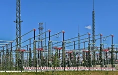
Electrical Substations
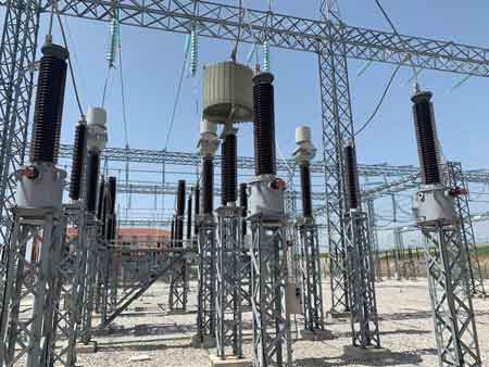
Capacitor Voltage Transformer in Substation
Latest Electrical Substations Articles
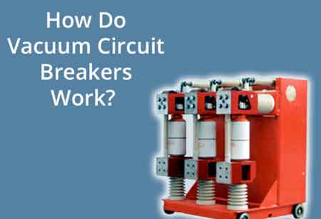
Vacuum Circuit Breaker Protection
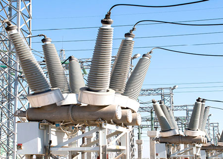
Circuit Breaker In Substation Explained
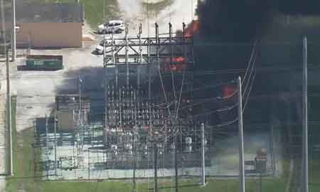
Substation Explosion
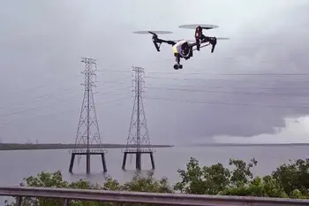
Construction Drones
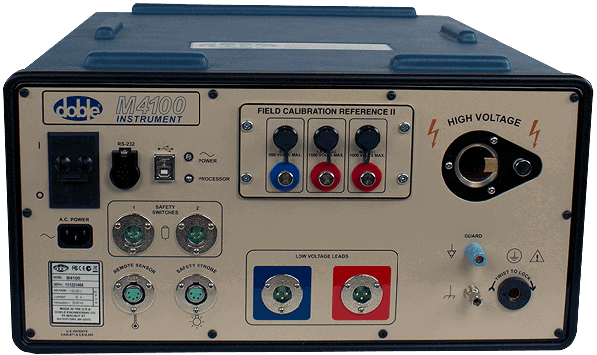
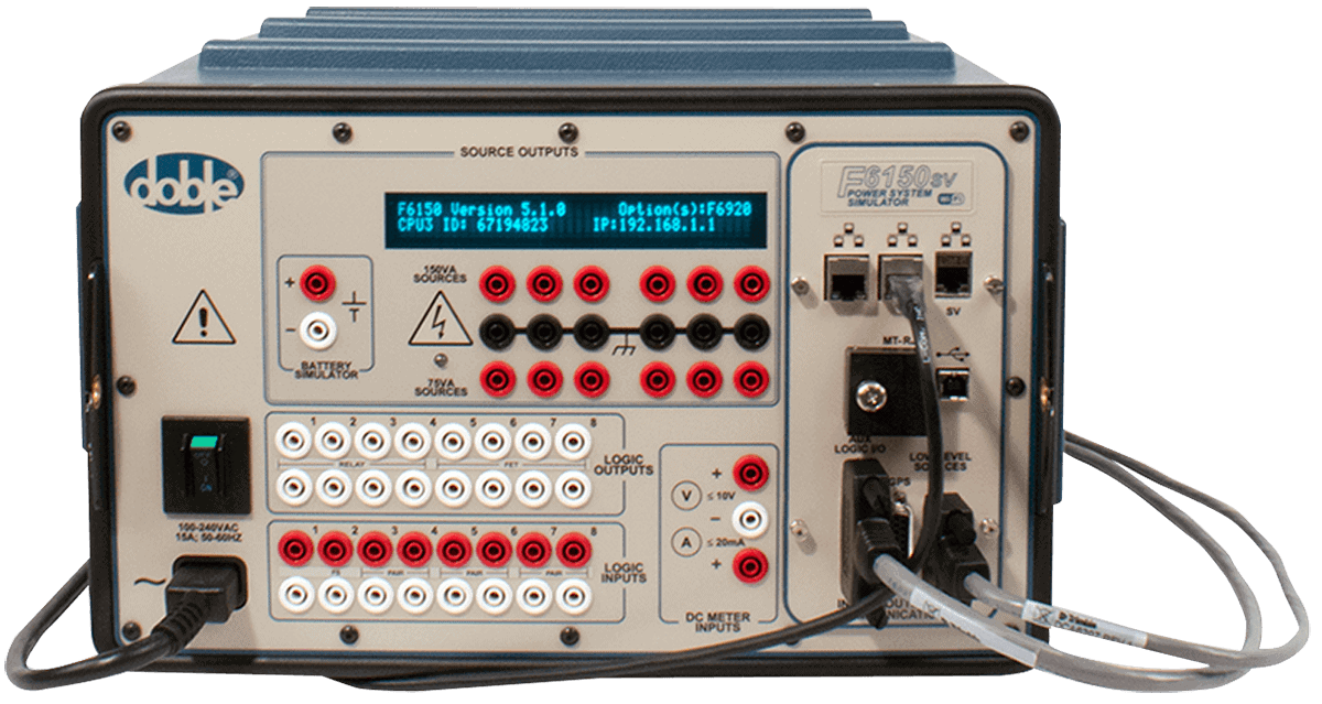
Doble Engineering
Doble Engineering Company is a global leader in diagnostic test equipment, software and engineering services for the electric power industry. Founded in 1920, it helps utilities and energy asset owners improve reliability, assess system health, and optimize operations through advanced diagnostics and expertise worldwide.
Contact us at sales@doble.com , or visit https://www.doble.com
Electrical Substations Articles From ET Magazine

AI at the Substation Edge: Digital Twins and Predictive Maintenance for Transformers and Switchgear
Inside the Digital Substation Upgrade: Migrating to IEC 61850 Ed. 2.1, Process Bus, and Interoperable Testing
Zero-Trust Substations: How CIP Is Shifting from Perimeter Defense to Continuous Vendor and Supply-Chain Risk Management

Grid Communications Infrastructure: Fiber, Wireless, and Networking Technologies
Sign Up for Electricity Forum’s Electrical Substations Newsletter
Stay informed with our FREE Electrical Substations Newsletter — get the latest news, breakthrough technologies, and expert insights, delivered straight to your inbox.
Electricity Today T&D Magazine Subscribe for FREE

- Timely insights from industry experts
- Practical solutions T&D engineers
- Free access to every issue

