Overhead T&D
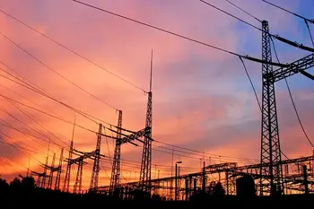
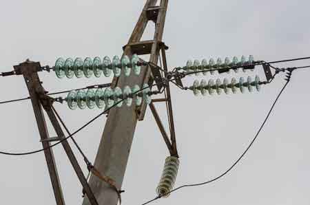
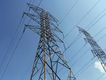
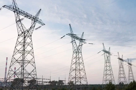
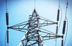
High Voltage AC Transmission Lines
Download Our FREE Overhead T&D Handbook
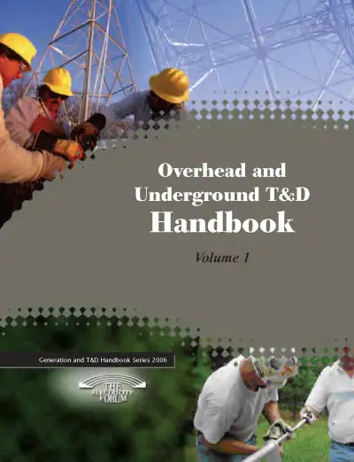
As utilities are faced with replacing rapidly aging transmission and distribution infrastructures, it is essential to be aware of the latest techniques, products and applications available on the market. Volume 1 of our Overhead & Underground T&D handbook series provides detailed information on testing and maintenance methods, the practical and theoretical applications of overhead transmission, and the unique challenges and opportunities presented by underground distribution networks. These topics and more are covered in detail in the 100-page first-volume handbook.
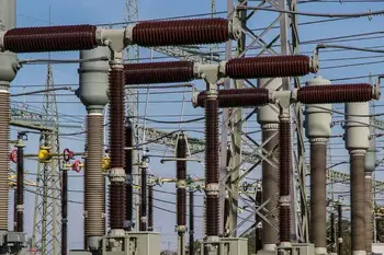
In this first volume, we explore the core principles and practices related to overhead and underground power transmission and distribution. We examine the key components of these systems, such as transmission lines, substations, transformers, cables, and switches, while delving into the design, installation, and maintenance of both overhead and underground configurations. Special attention is given to the unique challenges and considerations associated with each type of system—highlighting factors such as environmental conditions, reliability, safety standards, and operational efficiency.
This handbook is designed to assist engineers, utilities, technicians, and planners by providing practical insights and technical expertise for optimizing T&D systems. We cover essential topics such as grid infrastructure, fault detection, protection schemes, and the integration of emerging technologies like smart grids and renewable energy solutions. Whether you are involved in the planning of new installations or maintaining existing systems, Volume 1 offers the tools and guidance necessary for ensuring the safe and efficient delivery of power.
With a blend of theoretical concepts, industry best practices, and real-world applications, Overhead & Underground T&D Handbook, Volume 1 aims to be an indispensable reference for professionals seeking to deepen their understanding of transmission and distribution systems, and to navigate the evolving challenges of modern electrical networks.
Latest Overhead T&D Articles
Electric Power Distribution Delivery and Reliability
Reliability & Protection in Utility Distribution
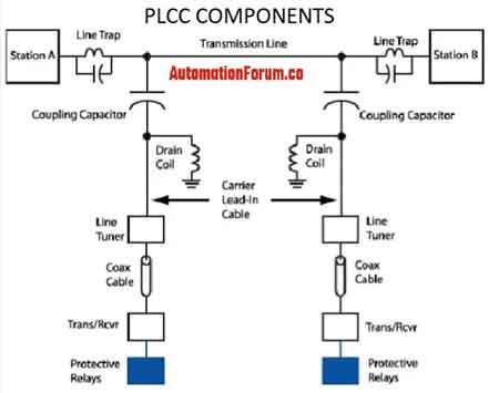
Power Line Carrier Communication Explained

Understanding How Overhead Switchgear Innovation Cost-Effectively

When it Comes To Digital Marketing, Novice Sailors Can Navigate Calm Waters But Rough Seas Require Expert Sailors...
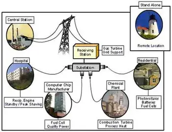
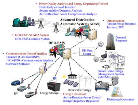
Distributed Energy Resources - Small Scale Power
Overhead T&D News
Overhead T&D Media


Overhead T&D Articles From ET Magazine
Transmission Construction Industry Leader Retires and Sells at Absolute Auction!
Why Net-Zero is Cheaper for the UK
FERC Complaint Targets Duke, PJM Transmission Planning
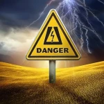
How Dangerous is Linemen Work?
Sign Up for Electricity Forum’s Overhead T&D Newsletter
Stay informed with our FREE Overhead T&D Newsletter — get the latest news, breakthrough technologies, and expert insights, delivered straight to your inbox.
Electricity Today T&D Magazine Subscribe for FREE

- Timely insights from industry experts
- Practical solutions T&D engineers
- Free access to every issue