Electricity Fundamentals

Electricity is a fundamental part of nature. Everything, from water and air to rocks, plants and animals, is made up of minute particles called atoms. They are too small to see, even with the most powerful microscope. Atoms consist of even smaller particles called protons, neutrons and electrons. The nucleus of the atom contains protons, which have a positive charge, and neutrons, which have no charge. Electrons have a negative charge and orbit around the nucleus. An atom can be compared to a solar system, with the nucleus being the sun and the electrons being planets in orbit.

Electrons can be freed from their orbit by applying an external force, such as movement through a magnetic field, heat, friction, or a chemical reaction.

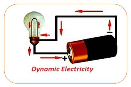
A free electron leaves a void, which can be filled by an electron forced out of its orbit from another atom. As free electrons move from one atom to another, an electron flow is produced. This electron flow is the basis of electricity.

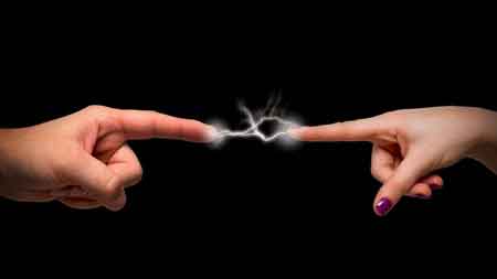
The cliché, "opposites attract," is certainly true when dealing with electrical charges.

Charged bodies have an invisible electrical field around them. When two likecharged bodies are brought close together, they repel each other. When two unlike charged bodies are brought closer together, their electrical fields work to attract.

Electricity Questions

What is an Electrical Circuit?

An electrical circuit is a closed loop that allows electric current to flow through conductors, power sources, and loads. Circuits connect electrical devices, enable energy transfer, and ensure safe operation in homes, industries, and power systems.


What is an Electrical Circuit?

An electrical circuit is a path through which electricity flows from a power source to one or more devices that are connected.

✅ Provides controlled current flow through conductors

✅ Powers electrical devices safely and efficiently

✅ Includes sources, loads, and protective components

Gaining a grasp of the basic electricity of electrical circuits, including series and parallel configurations, voltage, current, resistance, Ohm's Law, and circuit analysis techniques, is vital for anyone interested in electronics, electrical engineering, or the inner workings of modern technology.


Core Components & Function

In order to understand what an electrical circuit is, one must appreciate that, 

At its core, an electrical circuit is a closed loop or pathway that facilitates the flow of electric current. This concept is essential in electronics and electrical engineering, as it provides the basis for the operation of everyday items, including smartphones, computers, and home appliances.

Within an electrical circuit, components are connected via conductive materials, such as wires, which enable the movement of electrons from a power source to other components and back.

The primary components of an electrical circuit include a power source (e.g., a battery or power supply unit), conductive materials (typically wires), a load (such as a resistor, motor, or light bulb), and a control element (for example, a switch). The power source supplies the voltage necessary for electric current flow, while the load transforms electrical energy into other forms, such as light or heat. Meanwhile, the control element permits the user to initiate or halt the flow of electrons, effectively turning a device on or off.

  • For students, a simple example is a battery connected to an LED, which demonstrates how electricity creates light.

  • For professionals, an industrial motor powered by a control circuit shows how electrical energy drives large-scale equipment.


Circuit Types (Series vs. Parallel)

Electrical circuits can be classified into three main types: series, parallel, and combination circuits.

  • Series circuits connect components end-to-end, allowing current to flow sequentially through each one. Example: holiday string lights, where a single bulb outage can disrupt the entire circuit.

  • Parallel circuits enable current to flow through multiple paths. Example: household wiring, where turning off one light doesn’t affect others.

  • Combination circuits mix both series and parallel configurations to handle more complex systems.


Fundamental Laws (Ohm’s Law, Kirchhoff’s Laws)

A fundamental understanding of voltage, current, and resistance is crucial for comprehending electrical circuit operations.

Voltage, the driving force that propels electric charge through a circuit, and current, the flow of electric charge measured in amperes (A), are closely related to resistance. Resistance, expressed in ohms (Ω), represents the opposition to the flow of current. These elements are interconnected through Ohm's law, which states that the voltage across a conductor is directly proportional to the current it carries and inversely proportional to its resistance: V = IR, where V represents voltage, I denotes current, and R represents resistance. Understanding how current creates magnetic fields is explained by Ampere's Law, which forms the basis for analyzing electromagnetism in electrical circuits.

Circuit analysis determines the current, voltage, and power associated with each component in an electrical circuit. Techniques such as Kirchhoff's Law of voltage and current, Thevenin's theorem, and Norton's theorem are employed to analyze and resolve electrical circuit issues. These methods enable engineers to design and troubleshoot electronic devices and systems effectively.


Thevenin's Theorem

Thevenin's theorem is a fundamental principle in electrical engineering and circuit analysis. It is a powerful technique to simplify complex linear circuits, making it easier to analyze and calculate the current, voltage, and power across specific components. The theorem is named after the French engineer Charles Léonard Siméon Thévenin, who proposed it in 1883.


Thevenin's theorem states that any linear, active, bilateral network containing voltage sources, current sources, and resistors can be replaced by an equivalent circuit consisting of a single voltage source (called Thevenin's voltage, Vth) in series with a single resistor (called Thevenin's resistance, Rth) connected to the terminals of the original circuit. This simplified circuit, known as the Thevenin equivalent circuit, can then be used to analyze the behaviour of the original circuit with a specific load connected to its terminals.

Steps to apply Thevenin’s theorem:

  1. Identify the portion of the circuit you want to simplify and the terminals where the load will be connected.

  2. Remove the load from the terminals (if present) and leave the terminals open-circuited.

  3. Calculate the open-circuit voltage across the terminals. This value is Thevenin's voltage (Vth).

  4. Calculate the equivalent resistance seen from the open-circuited terminals with all independent voltage sources replaced by short circuits (zero resistance) and all independent current sources replaced by open circuits (infinite resistance). This value is Thevenin's resistance (Rth).

  5. Create the Thevenin equivalent circuit using the calculated Vth and Rth values, then connect the original load across the terminals.

Once the Thevenin equivalent circuit is determined, you can easily analyze the circuit's behaviour and calculate the current through the load, the voltage across the load, or even the power delivered to the load. This technique is particularly useful when analyzing circuits with varying loads or examining the circuit's behaviour at multiple points, as it simplifies calculations and saves time.


Norton’s Theorem

Norton's theorem is a fundamental principle in electrical engineering and circuit analysis that simplifies the analysis of complex linear circuits. Named after the American engineer Edward Lawry Norton, who introduced it in the early 20th century, the theorem is a counterpart to Thevenin's theorem.


While Thevenin's theorem reduces a complex network to an equivalent voltage source in series with a resistor, Norton's theorem simplifies the network to an equivalent current source parallel to a resistor.

Norton's theorem states that any linear, active, bilateral network containing voltage sources, current sources, and resistors can be replaced by an equivalent circuit consisting of a single current source (called Norton's current, IN) in parallel with a single resistor (called Norton's resistance, RN) connected to the terminals of the original circuit.

Steps to apply Norton’s theorem:

  1. Identify the portion of the circuit you want to simplify and the terminals where the load will be connected.

  2. Remove the load from the terminals (if present) and leave the terminals open-circuited.

  3. Calculate the short-circuit current flowing between the terminals. This value is Norton's current (IN).

  4. Calculate the equivalent resistance seen from the open-circuited terminals with all independent voltage sources replaced by short circuits (zero resistance) and all independent current sources replaced by open circuits (infinite resistance). This value is Norton's resistance (RN). Note that Norton's resistance is equal to Thevenin's, as both are calculated similarly.

  5. Create the Norton equivalent circuit with the calculated IN and RN values, connecting the original load across the terminals.

Once the Norton equivalent circuit is established, you can easily analyze the circuit's behaviour and calculate the current through the load, the voltage across the load, or even the power delivered to the load. Like Thevenin's theorem, Norton's theorem is particularly useful when dealing with varying loads or analyzing a circuit's behaviour at multiple points. In addition, it simplifies calculations, conserving time and effort.


Circuit Diagrams & Symbols

Circuit diagrams, also known as schematic diagrams, are graphical representations of electrical circuits that utilize standardized symbols to depict components such as resistors, capacitors, inductors, diodes, and transistors. These symbols facilitate the interpretation of a circuit's structure and function by engineers or hobbyists without requiring physical examination of the actual components.

Here are some common symbols used in circuit diagrams:

Resistor: A simple zigzag line represents a resistor, which opposes the flow of electric current and dissipates energy in the form of heat.

Capacitor: Two parallel lines with a small gap represent a capacitor. The positive plate is marked with a "+" sign in polarized capacitors, and a curved line represents the negative plate.

Inductor: A series of curved or looped lines, similar to a coil, represents an inductor, which stores energy in a magnetic field and opposes changes in current.

Diode: A triangle pointing to a line represents a diode, which allows current to flow in one direction but blocks it in the opposite direction.

Light-emitting diode (LED): Similar to a diode symbol, but with two arrows pointing away from the triangle, representing light emission.

Transistor: Two types of transistors are commonly used: bipolar junction transistors (BJTs) and field-effect transistors (FETs). A BJT symbol comprises a circle or rectangle with three connected leads (emitter, base, and collector). FET symbols are represented by a combination of lines and a vertical arrow with three terminals (gate, source, and drain).

Integrated circuit (IC): A rectangular or square box with multiple leads connected represents an integrated circuit, a complex assembly of numerous electronic components within a single package.

Battery: Alternating long and short parallel lines represent a battery, a source of electrical energy.

Power supply: A circle with an arrow pointing upwards or a combination of letters, such as "Vcc" or "+V," represents a power supply, which provides a constant voltage or current.

Switch: A break in line with an angled line nearby or a pair of lines connected by a diagonal line represents a switch, which controls the flow of current by making or breaking a circuit.

Ground: A series of horizontal lines that decrease in length, a downward-pointing arrow, or the letters "GND" represent a ground connection, which serves as a reference point and provides a return path for electrical currents.

These are just a few examples of the many symbols used in circuit diagrams. Therefore, it's essential to familiarize yourself with these symbols to read or create schematic diagrams for electrical or electronic circuits. The ability of a circuit to store electrical charge is described by Capacitance, a key principle in both electronics and power systems.


Practical Applications & Examples

Electrical circuits form the foundation of modern technology, enabling us to harness electricity to operate a wide range of devices and systems. From smartphones and computers to household appliances and industrial machines, circuits power nearly every aspect of daily life.

For example, a simple battery connected to a light bulb demonstrates how a closed loop allows current to flow, converting electrical energy into light and heat. Safe return paths for current are established through the proper installation of Grounding Electrode Conductors, which helps prevent shock and equipment damage.


Frequently Asked Questions


What is the simplest electrical circuit?

The simplest circuit consists of a power source (such as a battery), a conductor (like a wire), and a load (like a bulb). Closing the loop lets current flow and power the load.


How do series and parallel circuits differ in real life?

Series circuits share a single path, so if one component fails, the entire circuit stops. Parallel circuits have multiple paths, allowing devices to operate independently.


Why is grounding important in electrical circuits?

Grounding provides a safe return path for electricity. It reduces shock hazards and prevents equipment damage during faults or surges.


What role does resistance play in a circuit?

Resistance controls the amount of current flowing. High resistance limits current, while low resistance allows more current to pass.


What is the function of a circuit breaker or fuse?

These protective devices interrupt the current when it becomes too high, preventing overheating, fires, and damage to equipment. To safeguard devices and wiring from excessive currents, engineers rely on Overcurrent Protection Device such as fuses and circuit breakers.


What is an electrical circuit? Why It Matters

Electrical circuits are the backbone of modern technology, powering everything from smartphones and appliances to industrial systems. A firm grasp of fundamental circuit principles is crucial for engineers, electricians, and hobbyists, as it unlocks a deeper understanding of the devices that shape everyday life.


Related Articles


View more

What is a Resistor?

A resistor is an electronic component that limits or regulates the flow of electric current, manages voltage levels, and safeguards circuits in electrical and electronic devices, ensuring stable performance and preventing component damage.


What is a resistor?

A resistor is an electronic component designed to create electrical resistance in a circuit.

✅ Limits or regulates electric current flow in circuits

✅ Controls voltage levels for proper device operation

✅ Protects electrical and electronic components from damage

In electronic components and circuits, resistors play a crucial role. But what exactly is a resistor, and why are they so important? This comprehensive guide will explain the basics of resistors, explore different types and applications, and answer common questions related to their function and use. 

Their primary function is to control and limit the flow of electrical current, ensuring the proper operation of electronic devices and, in addition, introducing resistance to help maintain stable voltage and current levels in circuits, protecting sensitive components from damage due to excess current.


Electrical Resistance

Understanding electrical resistance is essential to grasping how resistors control current flow and protect sensitive components in circuits. The value of a resistor is determined by its electrical resistance, which is measured in ohms (Ω). Resistance is directly related to Ohm's law, a fundamental principle in electronics that states that the current (I) flowing through a conductor between two points is directly proportional to the voltage (V) across those points and inversely proportional to the resistance (R). In simpler terms, the equation V = I represents Ohm's law of R. Resistors work alongside capacitors and other components to regulate voltage and ensure stable performance in electronic devices. The unit of electrical resistance, the ohm (Ω), defines how much a resistor opposes the flow of electric current.

Various types of resistors are available, each with its own set of applications and characteristics. Some common resistor types include fixed resistors, variable resistors, carbon film resistors, metal foil resistors, metal oxide film resistors, and wire-wound resistors.

As the name suggests, fixed resistors have a fixed resistance value and are often used for general-purpose applications. Carbon film and metal film resistors are popular examples of fixed resistors, with the latter offering higher accuracy and stability. On the other hand, wire-wound resistors are constructed using a metal wire wrapped around a core, providing excellent heat dissipation and making them suitable for high-power applications.


Types of Resistors

Variable resistors, also known as potentiometers or rheostats, allow users to adjust the resistance manually. These components are typically used for fine-tuning and controlling various aspects of electronic circuits, such as volume or light intensity. Different types of resistors offer unique properties for specific applications, from precision electronics to high-power systems.

Resistor colour codes identify the value, tolerance, and sometimes the temperature coefficient of fixed resistors. The colour code consists of a series of coloured bands, with each colour representing a specific number. To read the colour code, you need to learn the number assigned to each colour and understand the sequence of bands.

The primary difference between fixed and variable resistors is the ability to adjust the resistance value. Fixed resistors have a predetermined resistance that cannot be changed, while variable resistors can be adjusted to obtain the desired resistance within a certain range.


Power Dissipation

Power dissipation is the heat a resistor generates when electrical current flows through it. This heat can affect the performance and reliability of a resistor and, in some cases, may cause damage to the component or the circuit. To prevent such issues, resistors are designed with a power rating, which indicates the maximum amount of power they can safely dissipate.

A resistor is integral to electronic circuits and can be found in virtually every electronic device. They come in various shapes, sizes, and materials to suit various applications. With their ability to control electrical current and maintain the stability of circuits, resistors play a vital role in the successful operation of electronic devices.


What is a resistor?

Resistors are essential electronic components that help regulate electrical current and voltage within circuits. Their various types and applications cater to different needs in the electronics world. Understanding resistors and their characteristics is crucial for anyone working with electronic circuits or looking to build their own devices.


Related Articles


View more

What is a Conductor?

A conductor is a material that allows electric current to flow easily due to its low resistance. Common conductors include copper and aluminum, used in electrical wiring and components. Conductors play a critical role in power distribution and circuit functionality.


What is a Conductor?

A conductor enables the flow of electricity or heat with minimal resistance. It's essential in electrical systems.

✅ Transfers electricity efficiently, commonly using copper or aluminum

✅ Used in wiring, power grids, and electronics

✅ Minimizes resistance for stable current flow

Understanding what a conductor is and how it functions is crucial to comprehending various aspects of modern life, including electricity, thermal management, and electronics. Conductors facilitate the flow of electrons and heat in various applications, while insulators impede these movements. Due to their unique properties and availability, copper, silver, and aluminum are good conductors of electricity. As a result, they are among the most commonly used conductor materials because they facilitate the flow of electricity. Factors affecting conductivity include atomic structure, temperature, and the purity of the material.

Conductors are an integral part of our daily lives, enabling the functioning of various devices and systems we depend on, such as electrical wiring and electronic devices. In contrast, thermal conductors facilitate heat transfer in numerous applications, from car engines to cookware. In addition, the unique category of semiconductors demonstrates that a material can possess both conductive and insulating properties, paving the way for the development of advanced technologies such as transistors and solar cells.


The Role of Conductors in Electricity

A conductor plays an essential role in the world of electricity. It enables the movement of electrons within a material, allowing electrical charge to flow smoothly through an electrical circuit. Electrical conductors consist of atoms that have loosely bound electrons, which are free to move and generate a current when an electric field is applied. This phenomenon is the basis for the flow of electrons in many electrical devices and systems.


Conductors and Insulators: The Key Differences

The primary difference between conductors and insulators lies in their ability to conduct electricity. While conductors, which are solid in nature, allow the flow of electrons, insulators impede this flow due to their tightly bound electrons. Consequently, insulators prevent electric shock or maintain electrical charge within specific boundaries. Good insulators include rubber, plastic, and glass.


Common Conductor Materials

The most commonly used materials for electrical conductors include copper, silver, and aluminum. Copper conductors are often preferred due to their excellent conductivity, relatively low cost, and high availability. Silver possesses the highest conductivity but is more expensive and less abundant. Aluminum is lightweight and affordable, making it an attractive choice for various applications such as power lines.


Factors Affecting Conductivity

The conductivity of a material depends on several factors, including its atomic structure, temperature, and purity. Materials with more free electrons or a regular atomic arrangement are more conducive. Temperature can also influence conductivity, as higher temperatures may cause the atoms in a material to vibrate more, leading to increased resistance. Purity is another essential factor, as impurities can impede the flow of electrons, reducing conductivity.


Applications of Conductors in Everyday Life

Conductors play a vital role in our daily lives, providing the foundation for many devices and systems that rely on the movement of electrons. Some notable examples include electrical wiring, power lines, and electronic devices such as computers and smartphones. Additionally, conductors are used in protective gear like fire-resistant clothing, which incorporates metal fibers to dissipate heat from the body.


Thermal Conductors: Function and Use

Thermal conductors allow heat to flow through them, effectively conducting heat from one area to another. This process is essential in many applications, such as in car engines, where conductors help dissipate heat away from the engine to prevent overheating. Thermal conductors are also found in household items, such as pots and pans, where heat must be transferred evenly for efficient cooking.


Can a Material be Both a Conductor and an Insulator?

In some cases, the material can exhibit both conductive and insulating properties. These materials are known as semiconductors, which possess a conductivity level between conductors and insulators. Silicon and germanium are two common examples of semiconductors. Semiconductors have numerous applications in electronic devices, including transistors and solar cells, which can regulate electrical current and convert sunlight into electricity.

As our understanding of conductors and their properties expands, we anticipate further innovations and improvements in the materials used in these essential components. For example, new conductor materials and composites could potentially be developed, offering better performance, higher efficiency, or enhanced durability. These advancements will contribute to the creation of even more sophisticated technologies and further enhance the quality of our everyday lives.


Related Articles


View more

What Is Alternating Current

Alternating current (AC) is a type of electrical flow where the direction of current reverses periodically. Used in most homes and industries, AC is efficient for long-distance transmission and powers devices like motors, lights, and appliances through oscillating voltage.


What is Alternating Current?

Alternating current is a fundamental aspect of electrical systems that have shaped our world in countless ways. Its ability to be easily generated, converted to different voltages, and transmitted over long distances has made it the preferred choice for power transmission and distribution. Additionally, the many advantages of AC, such as compatibility with various devices and safety features, have made it indispensable in our daily lives.

✅ Powers homes, businesses, and industrial equipment through reliable energy transmission.

✅ Changes direction periodically, unlike DC, which flows one way.

✅ Enables long-distance energy delivery with reduced power loss.


To answer the question: What is alternating current? We need to first understand the role of a conductor, which is essential in AC systems, as conductors carry the oscillating electrical energy throughout circuits.


Aspect Description Related Concept
Definition Electric current that periodically reverses direction, forming a sine wave. What is Alternating Current
AC vs. DC AC changes direction; DC flows in one direction only. Difference Between AC and DC
Waveform Typically sinusoidal, but can also be square or triangular. Impedance
Frequency Number of cycles per second (50 Hz or 60 Hz depending on the region). Unit of Electrical Resistance
Voltage Transformation Easily adjusted using transformers for long-distance transmission. Transformer Grounding
Measurement Tools Multimeters and voltmeters measure AC voltage and current. What is a Multimeter, What is a Voltmeter
Key Components Conductors, capacitors, resistors, and inductors are essential to AC systems. What is a Capacitor, What is a Conductor
Generation Principle Based on electromagnetic induction through rotating magnetic fields. Electromagnetic Induction
Common Applications Powering homes, industrial machines, and electrical grids. Electricity Grid
Inventor Nikola Tesla pioneered practical AC power systems and the induction motor. History of Electricity


Understanding AC and DC

In the world of electricity, there are two primary forms of electric current: alternating current (AC) and direct current (DC). Understanding the distinctions between these two types of currents and their applications in daily life is essential to appreciate the advances in electrical engineering and the technology that surrounds us. A multimeter is commonly used to measure AC voltage and current in residential and industrial electrical systems.


AC vs. DC: Basic Differences

AC and DC are two distinct methods by which electric charge is transferred through a circuit. AC involves the flow of charge that periodically reverses direction, creating a waveform typically resembling a sine wave. On the other hand, DC refers to the flow of charge in a single, constant direction. The differences in their nature, functionality, and applications create a contrasting landscape in the electrical power sector. Devices like the voltmeter are specifically designed to measure AC or DC voltage, helping technicians verify circuit functionality and safety.


Why AC Is Preferred for Power Transmission

One key reason why AC is preferred over DC is its ability to easily convert to and from high voltages, making electric power transmission across long distances more efficient. Additionally, transformers can increase or decrease AC voltage, resulting in minimal power loss during long-distance transmission. In contrast, DC power cannot be altered as conveniently, making it less suitable for power transmission over extended distances.


How Alternating Current Works

The working principle of AC is centred around the changing magnetic field created by the flow of electric current. As the current changes direction, the magnetic field also alternates, inducing a voltage in the nearby conductors. This property of AC is fundamental to the operation of AC generators and transformers.

  • AC operation is based on electromagnetic induction

  • Rreversal creates alternating magnetic fields

  • Voltage is induced in nearby conductors


The Role of Nikola Tesla in AC Development

The invention of AC can be attributed to multiple individuals, but the Serbian-American inventor, Nikola Tesla, is often credited with pioneering AC systems. Tesla's work on AC power transmission and his development of the induction motor helped establish AC as the dominant form of electricity.


Frequency: 50 Hz vs. 60 Hz

In frequency, the terms 50-cycle and 60-cycle AC refer to the number of times the current changes direction in one second. The frequency of AC power varies globally, with 50 Hz being the standard in many parts of Europe, Asia, and Africa, while 60 Hz is the norm in North America.

  • 50 Hz is standard in Europe, Asia, and Africa

  • 60 Hz is common in North America

  • Frequency affects compatibility and performance of electrical devices

This difference in frequency can affect the operation of certain appliances and devices, making it essential to use the appropriate frequency for the intended purpose.


Advantages of Alternating Current

The advantages of AC over DC extend beyond efficient power transmission. AC is easier to generate and is widely used for electric power generation, making it more accessible and cost-effective. Moreover, AC systems are safer as they can be easily switched off when required, reducing the risk of electrical accidents. AC is versatile and can power various devices, from small household appliances to large industrial machines.

Key benefits of AC:

  • Easily transformed to higher or lower voltages

  • Safer switching and control in circuits

  • Powers a wide range of residential and industrial devices


How AC Is Generated and Transmitted

The generation and transmission of AC are crucial components of the electrical power infrastructure. AC is generated through various means, such as hydroelectric, thermal, and nuclear power plants, which use generators to convert mechanical energy into electrical energy.

Transmission components:

  • Transformers: Adjust voltage levels

  • Transmission towers: Carry high-voltage lines

  • Substations: Regulate voltage for safe end-use

Once generated, AC is transmitted through power lines that consist of transformers, transmission towers, and substations, which adjust the voltage levels for efficient distribution and usage.


The Role of AC in Daily Life

AC plays a vital role in our daily lives, as it powers most of the appliances and devices we rely on, including lights, computers, and household appliances. In addition, its compatibility with transformers, ease of generation, and ability to transmit power over long distances make it a cornerstone of modern electrical systems.

Frequency has a notable impact on AC usage. In addition to determining the compatibility of devices with a region's power supply, the frequency of AC power affects the speed and performance of electrical motors. A change in frequency may result in the motor operating at a different speed or, in some cases, causing it to malfunction.

Transformers are essential devices in AC systems, as they adjust voltage levels to meet the requirements of various applications. They function by utilizing the principle of electromagnetic induction, where a changing magnetic field in the primary coil induces a voltage in the secondary coil. By adjusting the number of turns in the coils, transformers can efficiently increase or decrease the voltage of AC power, depending on the specific application's needs.

The differences between AC and DC are crucial in understanding the diverse landscape of electrical power. The invention of AC by Nikola Tesla and other inventors has revolutionized the way electricity is generated, transmitted, and utilized. With an appreciation for the characteristics and applications of AC, we can gain a deeper understanding of the technology and infrastructure that powers our world.


How Does Alternating Current Work?

AC works by periodically reversing the direction of the electric charge flow within a circuit. In contrast to DC, which flows in a constant direction, AC oscillates back and forth. This oscillation is typically represented as a waveform, often in the shape of a sine wave. Let's dive deeper into how AC works.

AC is characterized by a waveform that typically takes the shape of a sine wave, allowing for smooth and continuous changes in voltage over time. This makes it ideal for long-distance transmission across the power grid, where electricity generated by a generator must travel efficiently to homes and businesses. The frequency of this current—measured in cycles per second or hertz (Hz)—determines how rapidly the voltage changes direction, impacting device performance and grid efficiency. As current flows through a conductor, it can be stepped up or down using a transformer, enabling voltage levels to be optimized for safe and effective delivery.

Generation: AC is generated using a rotating magnetic field to induce an electric current in a conductor. This is done using devices such as generators and alternators, which convert mechanical energy into electrical energy. In these devices, a coil of wire rotates within a magnetic field, or a magnet rotates around a stationary coil. This rotation causes the magnetic field to interact with the conductor, inducing a voltage and, consequently, an electric current that changes direction periodically.

Waveform: The alternating nature of AC is depicted by a waveform, which shows the voltage or current as a function of time. The most common waveform for AC is the sine wave, which can also take other forms, such as square or triangular waves. The waveform's shape determines the characteristics of the AC and how it interacts with various electrical components.

Frequency: One important parameter of AC is its frequency, which indicates the number of complete cycles the current undergoes per second. It is measured in hertz (Hz). Common frequencies include 50 Hz and 60 Hz, but other frequencies can also be used depending on the application. The frequency of the AC power supply affects the performance and compatibility of devices and equipment connected to it.

Voltage and current relationship: In an AC circuit, the voltage and current can be in phase (i.e., they reach their peak values simultaneously) or out of phase (i.e., they reach their peak values at different times). The phase relationship between voltage and current in an AC circuit can significantly impact power delivery and system efficiency. A voltage sag can disrupt sensitive equipment, making voltage regulation a key part of power quality analysis.

Transformers: A key advantage of AC is that its voltage can be easily changed using transformers. Transformers operate on the principle of electromagnetic induction, where a changing magnetic field in the primary coil induces a voltage in the secondary coil. By adjusting the number of turns in the coils, the transformer can step up or down the AC voltage as needed. This ability to adjust voltage levels makes AC an efficient choice for long-distance power transmission.


Frequently Asked Questions


What is the formula to calculate alternating current?

To calculate the value of AC at any given time, you need to know the current's amplitude (maximum value) and the angular frequency. The general formula for calculating instantaneous current in an AC circuit is:

i(t) = I_max * sin(ωt + φ)

Where:

  • i(t) is the instantaneous current at time t

  • I_max is the amplitude or peak current

  • ω (omega) is the angular frequency, calculated as 2πf (where f is the frequency in hertz)

  • t is the time at which you want to calculate the current

  • φ (phi) is the phase angle, which accounts for any phase shift between the voltage and the current waveforms

Remember that this formula assumes a sinusoidal waveform, the most common form of AC. If the waveform is not sinusoidal, the formula will be different and depend on the specific shape of the waveform.

Another important value for AC circuits is the root-mean-square (RMS) current, which measures the effective value of the current. The RMS current is useful for calculating power in AC circuits and can be compared to the steady current value in DC circuits. The formula to calculate RMS current from the peak current is as follows:

I_RMS = I_max / √2

Where:

  • I_RMS is the root-mean-square current

  • I_max is the amplitude or peak current

  • √2 is the square root of 2, approximately 1.414

  • Using these formulas, you can calculate the instantaneous current value for an alternating current waveform and determine the effective or RMS current value.

To understand how voltage affects electrical circuits, it's essential to examine how voltage drop can lead to energy loss, particularly over long distances.


Related Articles


View more

Electrical Short Circuit

An electrical short circuit occurs when current takes an unintended path with low resistance, resulting in excessive heat, arc faults, or increased fire risks. Proper circuit protection, insulation, and grounding methods are vital for preventing damage.


What is an Electrical Short Circuit?

An electrical short circuit is an abnormal condition in which electricity bypasses normal wiring paths, causing high current flow and serious hazards.

✅ Results in overheating, arc faults, or fires

✅ Requires protective devices and grounding for safety

✅ Demands inspection, risk assessment, and prevention

This dangerous event can result in power outages, damaged appliances, or even fires. By understanding the types of short circuits, their causes, detection methods, and prevention strategies, we can greatly reduce the risks. When studying short circuits, it is helpful to first understand the principles of basic electricity, as the same laws of voltage, current, and resistance explain why faults occur.


Causes of Short Circuits

There are several reasons why a short circuit may occur. Common causes include faulty appliance wiring, loose wire connections, and damaged insulation on wires. These issues can lead to current flowing through an unintended path, creating a short circuit.

Short circuits happen for many reasons, ranging from everyday wear to unusual accidents:

  • Damaged or faulty wiring – Insulation breakdown from age or overheating.

  • Water or moisture ingress – Flooding, leaks, or humidity can allow current to bypass insulation.

  • Pest damage – Rodents chewing wiring can strip insulation and create direct shorts.

  • Mechanical damage – Nails, drilling, or physical stress on cables.

  • Corrosion in connections – Loose or corroded joints create hot spots and unintended paths.

  • Appliance defects – Internal failures in motors, compressors, or electronics.

  • Ground faults vs. short circuits – A short is current between conductors, while a ground fault involves current leaking to earth.

  • Overload vs. short – Overload is too much current for too long; a short is a sudden surge with very low resistance.


Detection and Symptoms

Detecting a short circuit can be challenging, but some common signs may indicate its presence. Detecting a short circuit can be difficult, but common warning signs include:

  • Frequent tripping of breakers or GFCIs

  • Flickering or dimming lights

  • Buzzing or crackling sounds in outlets

  • Burning smells or discolored outlets

  • Damaged insulation or melted wires

For diagnosis, electricians use multimeters, insulation testers (meggers), clamp meters, and thermal imaging cameras to isolate fault locations. Tracers can also help locate hidden shorts inside walls. In three-phase systems, a fault between conductors can cause even greater hazards, making it essential to understand how three-phase electricity behaves under fault conditions. Ground faults are often confused with shorts, but a true electrical fault may involve multiple types of abnormal current flow.


Theory of a Short Circuit

A short circuit illustrates Ohm’s Law (V = I × R): when resistance (R) drops close to zero, current (I) increases dramatically. This sudden fault current stresses wiring, overheats insulation, and can exceed equipment ratings. That’s why time-current curves, protective relays, and properly sized conductors are crucial for safety. Protective devices are designed to limit current and prevent excessive electrical resistance heating that can trigger a fire.


Prevention

Prevention is key to safety. Prevention is the most effective protection. Strategies include:

  • Installing arc fault circuit interrupters (AFCIs) to detect dangerous arcs.

  • Using fuses, breakers, and GFCIs for fault interruption.

  • Adding surge protectors to handle transient spikes.

  • Ensuring proper conductor sizing and insulation quality.

  • Using protective relays and redundancy in industrial systems.

  • Regular inspections of cords, outlets, and panels.

Modern codes, such as the National Electric Code (NEC), the Canadian Electric Code, and IEC standards, all require specific protection and device ratings to reduce hazards.


Dangers of Short Circuits

Short circuits can pose significant risks to both people and property. They are among the most dangerous faults:

  • Fire hazards – Sparks and overheated wires ignite flammable materials.

  • Electric shock – Fault currents may flow through people during contact.

  • Equipment damage – Motors, appliances, and electronics can be severely damaged or destroyed.

For example, a refrigerator's shorted compressor can ignite nearby insulation, while an industrial panel's short can trip upstream breakers, causing outages and costly downtime. They are one of the many dangers of electricity that electricians must guard against through the use of insulation, grounding, and protective equipment.


How To Repair

If you suspect a short in the power system, it's crucial to address the issue immediately. If you suspect a short:

  1. Shut off the power at the breaker or unplug devices.

  2. Inspect outlets, cords, and panels for visible damage.

  3. Use diagnostic tools to isolate the faulted loop.

  4. Replace damaged wires or devices.

  5. If uncertain, consult a licensed electrician — shorts are not DIY-friendly.


Difference Between a Short Circuit and an Open Circuit

While both short circuits and open circuits involve disruptions in normal functioning, they are fundamentally different. A short occurs when the current flows through an unintended path, resulting in a sudden surge in current. In contrast, an open path is a break in its continuity, which stops the flow of current altogether. Both situations can cause problems in your system and should be addressed promptly.


Frequently Asked Questions


Can a short circuit happen in a GFCI outlet?

Yes. GFCIs protect against ground faults, but not all types of shorts. Breakers and fuses are still required.


How often should wiring be inspected?

Residential wiring should be inspected every 5–10 years, or immediately if signs of overheating or frequent breaker trips are observed.


What is the difference between a ground fault and a short circuit?

A ground fault involves current flowing into earth, while a short occurs between conductors. Both are hazardous.

Understanding shorts — their causes, detection, prevention, and associated risks — is crucial for safeguarding people and property. Regular inspections, proper protection, and adherence to codes all reduce hazards. If you suspect a short, act immediately and contact a qualified electrician.


Related Articles


View more

What Is Static Electricity?

Static electricity is the accumulation of electrical charge on an object’s surface, usually from friction, induction, or contact. This imbalance of electrons and protons creates sparks, shocks, and attraction, influencing physics, electronics, and everyday energy phenomena.


What is Static Electricity?

Static electricity occurs when an imbalance of electric charges exists within or on the surface of a material. It results from the movement of electrons, negatively charged particles that orbit the nucleus of an atom. At its core, static electricity is one aspect of electrical behavior—if you’d like to explore foundational concepts like charge and energy flow, see what is electricity.

✅ Caused by friction between materials, transferring electrons

✅ Can result in mild electric shocks or static cling

✅ Affects electronics, dust attraction, and insulation needs

Atoms also consist of positively charged particles called protons and neutral particles called neutrons. When an object gains or loses electrons, it becomes positively or negatively charged.


How Static Electricity Forms

Static electricity occurs when a static electric charge builds up on the surface of a material, often resulting from friction or the separation of objects. This phenomenon, commonly referred to as static, occurs when negative charges—specifically, electrons—accumulate in one area, creating an imbalance. When conditions allow, electrons jump suddenly to another surface to neutralize this difference, sometimes producing a visible spark or mild shock. Unlike materials that easily conduct, electrical insulators tend to trap these charges, making static buildup more likely.

Static electricity arises when there is an imbalance of charges, specifically, when electrons are transferred from one material to another. This can happen through two primary mechanisms: the triboelectric effect and electrostatic induction. To understand how electric charges interact in circuits, explore what is an electrical circuit and how current flow differs from static buildup.


Triboelectric Effect

When two different materials come into contact and then separate, electrons move from one surface to the other. The object that loses electrons becomes positively charged, and the one that gains them becomes negatively charged. This is the most common way static electricity is created.

  • Clothes sticking after being dried

  • A balloon clinging to a wall after rubbing on hair


Electrostatic Induction

Unlike the triboelectric effect, induction involves no direct contact. A charged object brought near a neutral object can cause electrons within the neutral object to shift positions, creating areas of opposite charge. This redistribution allows static electricity to form without touching. Since friction between insulating materials often generates static charge, it’s helpful to know what is a conductor and what is an insulator.


Conductors vs. Insulators

The behavior of static electricity largely depends on the type of material involved. Some materials allow charge to flow freely, while others trap it.

Insulators prevent the free movement of electrons, allowing charge to build up on their surfaces. Common insulators include rubber, plastic, and glass. Conductors, on the other hand, permit electrons to move easily, which helps dissipate static buildup. Metals like copper and aluminum are typical conductors. To understand how material properties affect charge buildup and dissipation, visit what is a conductor and what is electrical resistance.

  • Insulators hold static charge and are prone to build up

  • Conductors allow electrons to flow, preventing accumulation

  • Static electricity often forms between two insulating surfaces


Electrostatic Discharge (ESD)

A sudden movement of static electricity from one object to another is known as electrostatic discharge, or ESD. This release can happen in a fraction of a second and may result in a visible spark or a mild electric shock.

Though often harmless in daily life, ESD can be hazardous in industrial settings. It can ignite flammable vapors or damage sensitive electronic components.

  • Shocks from doorknobs or car doors

  • Sparks in dry environments

  • Damage to circuit boards and microchips

This process is driven by a difference in electric potential. To explore this concept further, visit what is voltage.

The behavior of electrons in materials also relates to what is capacitance, a key concept in storing electrostatic energy.


Real-World Examples

Static electricity isn’t just theoretical—it manifests in many everyday situations, often in surprising or frustrating ways.

  • Static cling in laundry

  • Hair standing on end in dry air

  • A comb attracts small bits of paper

  • Lightning storms—giant-scale electrostatic discharge


How to Prevent Static Electricity

Managing it, especially in dry environments or around sensitive equipment, is essential. Thankfully, there are several simple and effective insulator materials to reduce static buildup at home or in the workplace.

  • Use humidifiers to increase air moisture

  • Apply antistatic sprays to fabrics and carpets

  • Wear natural fibers instead of synthetics

  • Touch grounded metal before handling electronics

  • Use antistatic wristbands or grounding mats when working on computers

Preventing shocks is part of general electrical safety, see dangers of electricity for more on how electrostatic discharge fits into the broader picture of electrical hazards.


Differences Between Static and Current Electricity

Although both involve electric charge, static electricity and current electricity behave very differently. Understanding the contrast helps explain why one causes shocks and the other powers devices.

Feature Static Electricity Current Electricity
Charge Movement Stationary Flows through a conductor
Source Friction or induction Battery, generator, power source
Use in Devices Limited Essential for powering devices

To better understand flowing charge and how it contrasts with static buildup, visit what is current electricity.


Applications of Static Electricity

Electrostatic force is more than a nuisance — it has practical applications across several industries. Scientists and engineers use electrostatic principles to solve real-world problems and improve everyday technologies.

  • Electrostatic precipitators filter pollutants from factory exhaust

  • Laser printers and copiers use static charge to transfer toner

  • Paint sprayers evenly coat surfaces using electrostatic attraction

  • Electrostatic generators like the Van de Graaff produce high voltages for demonstrations and research


Demonstrating Static Electricity

You don’t need a lab to see the electrostatic force in action. Simple household materials can illustrate how this invisible force works.

  • Rubbing a balloon on your hair and sticking it to a wall

  • Combing dry hair and attracting paper pieces

  • Using a Van de Graaff generator to make hair stand on end


The electrostatic force is the force that holds these positive and negative charges together or pushes them apart. When two objects come into contact, the triboelectric effect can transfer electrons from one object to the other. This causes both objects to become charged, with one gaining electrons and becoming negatively charged and the other losing electrons and becoming positively charged.

Insulators and conductors play a crucial role. Insulators are materials that do not allow extra electrons to flow freely, such as rubber, plastic, or glass. Conductors, on the other hand, are materials like metals that easily enable electrons to flow. When two insulators come into contact, they are more likely to generate a static charge, as electrons cannot easily move between them. 


Frequently Asked Questions

What causes static electricity?

It’s caused by either the triboelectric effect (contact and separation) or electrostatic induction (non-contact charge redistribution).


What is electrostatic induction?

It’s when a nearby charged object causes the electrons in another object to shift, without any physical contact.


Why does it cause shocks?

Because the excess charge seeks to neutralize, jumping to a grounded object like your body, creating a quick discharge.


Is it dangerous?

Yes, in some cases. It can ignite flammable gases or damage delicate electronics through electrostatic discharge.


How can I prevent static buildup at home?

Keep humidity levels up, avoid synthetic materials, and use grounding methods like touching metal before contact.


What are industrial safety measures?

Professionals use ESD-safe tools such as antistatic wristbands, mats, and ionizing blowers to prevent damage and injury.

As we've explored, electrostatic charge imbalance is an intriguing and complex phenomenon influencing various aspects of our lives. From the simple yet surprising instances of hair standing on end to the practical applications in industries, understanding and harnessing this force can open up new possibilities in science, technology, and even our daily routines. By continuing to study and explore static electricity, we can unlock its full potential and utilize it to enhance our lives in numerous ways, making them better and more efficient. 

It is a captivating subject that permeates our lives in various ways. By understanding the science behind it, we can better appreciate its effects, take precautions to avoid potential hazards, and explore its myriad applications in technology and industry. Moreover, as we continue to learn more about this invisible force, we can undoubtedly find new ways to harness and utilize it in our everyday lives and beyond.


Related Articles


View more

What is Electric Load

Electric load refers to the amount of electrical power consumed by devices in a system. It determines demand on the power supply and affects energy distribution, efficiency, and system design.


What is Electric Load?

✅ Measures the power consumed by electrical devices or systems

✅ Impacts system design, energy use, and load management

✅ Varies by time, usage patterns, and connected equipment

What is electric load? It refers to the total power demand placed on a circuit by connected devices. Electric load, such as lighting, motors, and appliances, impacts energy use, system sizing, and overall efficiency across residential, commercial, and industrial settings.

An electric load refers to any device or system that consumes electric power to perform work, such as an electric motor, lighting fixture, or household electrical appliances. These loads draw electrical energy from the power source, impacting both system efficiency and capacity planning. Accurate electrical load calculation is crucial for designing circuits, selecting the correct breakers, and ensuring safe operation in homes, businesses, and industrial facilities. Using real-time monitoring tools, engineers can assess load patterns, identify peak demand, and implement energy-saving strategies through smart load management systems.

An electric load can be anything that consumes power, such as lights, appliances, heating systems, motors, and computers. In electrical engineering, a load represents the demand that a device or installation places on the power source.

Electric load is closely influenced by regional consumption patterns, which can be explored in more detail in Electricity Demand in Canada, highlighting how climate and industry shape national power usage.

Different types of types exist, and they are classified based on their characteristics. Resistive loads include, for example, converting energy directly into heat, such as heaters or incandescent light bulbs. Inductive loads, however, require energy to create a magnetic field, such as motors or transformers. Capacitive loads, meanwhile, store and release energy, such as capacitors used in a powered circuit.


An electric load refers to any device or circuit that consumes energy in a system. A common example is a load that consists of appliances such as heaters or ovens, where the primary component is a heating element. This heating element converts energy into heat, providing warmth or cooking power. It consists of a heating mechanism that demands specific amounts of powered energy depending on the device’s power requirements, which is crucial for maintaining an efficient and balanced system. For readers new to electrical concepts, the Basic Electricity Handbook provides foundational knowledge that helps contextualize the meaning of electricity in power systems.


Types of Electrical Loads

Electric loads fall into three primary categories:

  • Resistive: Devices like incandescent light bulbs, heaters, and toasters. These convert energy directly into heat.

  • Inductive: Motors, transformers, and fans. Inductive loads create magnetic fields to operate, often resulting in a lagging power factor.

  • Capacitive: Capacitors are used in power factor correction equipment or some specialized electronic devices. They store energy temporarily.

Each load type interacts differently with the system, impacting both efficiency and stability.

Related: Understand how resistive loads behave in a circuit.


How to Calculate Electric Load

Accurately calculating electric load is important for selecting the correct wire size, circuit breakers, and transformer ratings.


For example:

  • If a device operates at 120 volts and draws 5 amps:

    • Load = 120 × 5 = 600 watts


Step-by-Step Example for a Household Circuit:

  1. Add up the wattage of all devices on the circuit.

  2. Divide the total wattage by the system voltage to find the total current load.

  3. Compare the load to the circuit breaker rating to ensure it is not overloaded.

Tip: Always design for 80% of breaker capacity for safety.


Why Understanding Electric Load Matters

Understanding electric load has real-world implications:

  • Energy Bills: Higher demand results in higher costs, particularly for businesses subject to demand charges.

  • System Design: Correct assessment ensures that wiring, transformers, and protection devices are appropriately sized.

  • Power Quality: Poor management can lead to low power factor, voltage drops, and even system instability.

  • Maintenance Planning: Predictable loads extend the life of equipment and reduce costly downtime.


Management Strategies

Smart load management can improve system efficiency and reduce costs:

  • Peak Shaving: Reducing consumption during periods of high demand.

  • Shifting: Moving heavy loads to off-peak hours.

  • Power Factor Correction: Installing capacitors to improve system efficiency and lower bills.


Electric load is a critical concept in both residential and industrial settings. By understanding the types of calculations used to determine total demand and the practical impacts on energy costs and system design, you can build safer, more efficient systems.

One critical aspect is the power factor. Power factor is the ratio of active power (measured in watts) to apparent power (measured in volt-amperes). In simpler terms, it is the efficiency of energy usage. A low power factor indicates that a device or system consumes energy more than necessary to perform a given task, leading to higher energy costs and increased strain on the power grid. The relationship between load, bill, and motor is especially evident in provincial models, such as Ontario’s Electricity Cost Allocation, which explains how peak demand affects consumer rates.

An electric load is a critical concept in the design and operation of the power grid. Understanding how it is measured, the different types, power factor, management strategies, peak, shedding, and demand response programs are essential for optimizing the use of the grid and ensuring its reliability. By balancing the demand for power with the grid's capacity, we can reduce energy costs, prevent blackouts, and create a more sustainable energy system. Management is a critical component of infrastructure planning, as discussed in the Transmission & Distribution Channel, which examines how levels affect grid design and performance.

In industrial environments, managing efficiently can lead to significant cost savings and operational stability. Explore these strategies in the Industrial Electric Power Channel.


View more

What is an Arc Fault?

An arc fault is a dangerous electrical discharge between conductors or to ground. It generates intense heat and light, often caused by damaged insulation, frayed wires, or loose connections, posing major electrical safety and fire hazards.


What is an Arc Fault?

An arc fault is an unintended electrical discharge that occurs when insulation or wiring fails, producing dangerous heat that can ignite fires and damage circuits.

✅ Caused by frayed wires or loose connections

✅ Produces intense heat and light energy

✅ Prevented by Arc Fault Circuit Interrupters (AFCIs)


Basic Protection Relay Training

Short Circuit Study Training

Request a Free Training Quotation


Understanding Arc Faults and Electrical Safety

An arc fault is a hazardous electrical event that can lead to severe consequences, including fires and substantial property damage. Understanding how faults occur, how to prevent them, and why protective measures like Arc Fault Circuit Interrupters (AFCIs) are essential can significantly improve home and workplace safety.

When electrical current jumps across a gap or an unintended path, it forms an electric arc. This arc generates extremely high temperatures—often exceeding 10,000°F—capable of igniting nearby insulation, wood framing, or other combustible materials. Faults are typically caused by damaged, frayed, or aging wiring, loose terminal connections, or punctured cables from nails and screws during construction. For more insight into advanced safety devices, learn how an arc fault interrupter breaker detects hazardous arcing and disconnects power before a fire can start.

Arc fault protection is especially important in areas where people live and spend time, such as family rooms, dining rooms, and living rooms, where electrical wiring runs behind walls containing materials such as wood framing or insulation that can easily ignite. Modern safety standards, as mandated by the National Electrical Code, require the installation of Arc Fault Circuit Interrupters (AFCIs) in these spaces to prevent fires caused by faults. When combined with Ground Fault Circuit Interrupters, which protect against electrical shock, AFCIs provide comprehensive protection against both fire and shock hazards in residential and commercial environments.


Types of Arc Faults

Arc faults can appear in different forms, each with its own risks and detection requirements:

  • Series Faults – Occur along a single conductor, usually from a broken wire or loose terminal. These arcs produce less current but can still ignite fires.

  • Parallel Faults – Form between two conductors (hot-to-neutral or hot-to-ground). These faults create higher current levels and more intense arcing.

  • Ground Faults – Happen when current leaks or shorts to a grounded surface, such as a metal outlet box or appliance casing. Explore how ground fault protection complements AFCIs by guarding against current leakage that could cause electric shock or parallel arc conditions.

Recognizing these types helps electricians and inspectors identify the right protection strategies and select appropriate AFCI devices. To see how fault current behavior impacts fault risks, review our explanation of available fault current and why accurate short-circuit studies are essential for system safety.


How AFCI Detection Works

AFCIs are intelligent safety devices designed to detect the unique electrical signatures of faults. They continuously monitor current waveforms and frequencies, distinguishing dangerous arcs from normal switching arcs (such as those produced by light switches or vacuum cleaners).

When an AFCI identifies an abnormal frequency pattern consistent with arcing, it trips the circuit within milliseconds—disconnecting power before the fault can ignite a fire. This advanced “signature detection” technology is required by modern safety codes and has saved countless lives and properties. For more insight into advanced safety devices, learn how an arc fault interrupter breaker detects hazardous arcing and disconnects power before a fire can start.


Limitations and Nuisance Tripping

While AFCIs are highly effective, they can occasionally cause nuisance tripping. This occurs when the device misinterprets harmless electrical noise as a fault, typically triggered by motors, dimmers, or other electronic devices. Regular inspection, proper grounding, and updated AFCI models help minimize these false positives. If nuisance tripping persists, it’s advisable to have an electrician verify circuit wiring and device compatibility. To understand how electrical systems respond to fault conditions, refer to our detailed explanation of protective relay coordination, which ensures that circuit breakers isolate faults without disrupting unaffected circuits.


Code Requirements and Standards

Arc fault protection is mandated by both U.S. and Canadian electrical codes:

  • National Electrical Code (NEC 210.12) requires AFCI protection for all 120-volt, single-phase, 15- and 20-amp branch circuits supplying living areas such as bedrooms, family rooms, dining rooms, and similar spaces.

  • Canadian Electrical Code (CEC Section 26) similarly mandates AFCI in dwelling units.

  • IEEE 1584 provides calculation guidelines for flash hazards in industrial power systems, complementing residential and commercial fault safety standards.

Following these standards ensures compliance and dramatically reduces fire risks across residential, commercial, and industrial applications.


Statistics and Case Studies

According to the U.S. Consumer Product Safety Commission (CPSC), electrical fires cause over 51,000 residential fires annually, resulting in more than 500 deaths and $1.3 billion in property damage. Studies show that AFCI protection can prevent more than half of these incidents, highlighting its critical role in modern electrical safety systems.


Emerging Technologies in Arc Fault Detection

New generations of AFCIs utilize microprocessors and artificial intelligence to enhance accuracy and minimize false trips. These smart devices analyze waveform patterns with greater precision, detecting high-impedance arcs and subtle irregularities. Future technologies may integrate predictive analytics and IoT monitoring to diagnose potential faults before they become hazards. Finally, explore comprehensive methods of electrical surge protection, which safeguard sensitive equipment from voltage spikes often linked to lightning events.


Common Causes of Arc Faults

  • Damaged or aging electrical wiring

  • Loose terminal connections in outlets or switches

  • Overloaded circuits or faulty appliances

  • Nails or screws penetrating electrical cables

  • Deteriorated insulation from heat, moisture, or rodents

Regular maintenance and periodic inspections by a licensed electrician are essential preventive measures.


Arc Fault vs Ground Fault vs Short Circuit

Fault Type Description Main Hazard Protection Device
Arc Fault Unintended arcing between conductors or within wiring Fire risk AFCI
Ground Fault Current flowing to ground unintentionally Electric shock GFCI
Short Circuit Direct contact between conductors High current / equipment damage Circuit Breaker

Understanding these differences helps ensure that electrical protection systems are properly matched to the specific hazards they are intended to address.


Frequently Asked Questions


Why does my AFCI keep tripping?

Often due to electronic interference, shared neutrals, or actual wiring issues. Replace outdated AFCIs and consult a professional if tripping persists.


Can I retrofit AFCIs into older panels?

Yes. AFCI breakers can replace standard breakers in most modern panels. Have a qualified electrician confirm compatibility before installation.


Are AFCIs required everywhere?

While required in most living spaces, some regions exempt areas like garages or unfinished basements. Check the NEC or CEC requirements for your jurisdiction.


Related Articles


View more

Electricity Fundamentals

Dynamic Electricity Explained

Dynamic electricity is the continuous flow of electric charge—electric current—through a conductor, typically driven by a voltage source. Think of it like water flowing in a pipe, where electrons move uniformly to carry energy.


What is Dynamic Electricity?

Dynamic electricity refers to the continuous movement of electric charges, commonly known as electric current.

  • Describes the flow of electrons or electric charge through a conductor

  • Facilitates energy transfer, enabling devices and machines to operate

  • Used in powering household appliances, industrial processes, lighting, and electronics

It is the continuous flow of electric charges through a conductor, commonly referred to as electric current. Think of it like water flowing through a pipe: voltage acts as water pressure, current as the flow of water, and resistance as the size of the pipe. This motion of electrons is what powers devices, lights homes, and drives entire industries.

Unlike static electricity, which involves charges at rest, dynamic electricity is defined by the constant movement of charge carriers, making it the foundation of modern electrical systems. To understand how voltage, current, and resistance interact in circuits, see our detailed guide on Ohm’s Law.

It depends on the movement of charges through conductive materials. Learn more about the difference between conductors and electrical insulators.

Dynamic electricity is closely tied to the concept of electrical energy, which is produced when an energy source creates movement between charges. A negative charge is naturally drawn toward a positively charged region, and objects with opposite charges will attract one another. This interaction between positive and negative charges is the foundation of current flow. Every type of electrical system, from simple batteries to complex power grids, relies on this basic principle to generate and transfer usable energy.


How It Works (Voltage, Current, Ohm’s Law)

Dynamic electricity occurs when a voltage difference is applied across a conductor, such as copper or aluminum wire. This creates an energy imbalance that causes electrons to flow from one end to the other.

  • Electrons drift slowly, but the electrical effect travels nearly at the speed of light, allowing instant energy transfer.

  • The flow of current is governed by Ohm’s Law: V = IR, where voltage (V) equals current (I) times resistance (R).

  • Moving charges generate magnetic fields and produce heat, demonstrating the role of resistance in circuits and enabling the operation of motors, electromagnets, and heating devices.

  • Current is measured in amperes (A), typically using an ammeter or other measurement instruments.

Electric current is measured in amperes, a unit explained in our introduction to electrical current.

The safe handling of flowing charges requires proper electrical grounding techniques to prevent hazards.

Analogy: Imagine marbles in a tube. Push one marble in, and the entire line shifts almost instantly. Similarly, electron movement is slow, but the effect propagates quickly through the entire circuit.


AC vs DC Explained

Type of Current Description Common Uses Advantages
Direct Current (DC) Electrons flow in a single, steady direction Batteries, electronics, solar panels, EVs Stable output, essential for digital devices and storage systems
Alternating Current (AC) Electron flow reverses direction periodically Power grids, appliances, and industrial systems Efficient long-distance transmission, adaptable to transformers


  • Why AC? Its ability to change voltage levels makes it ideal for transmitting energy over long distances with minimal energy loss.
  • Why DC? Critical for low-voltage devices, renewable integration, and battery storage, where stable current is required.

For a deeper look at how alternating current functions in grids, see our overview of alternating current.

Direct current plays a vital role in storage and electronics. Explore its applications on our page on direct current.


Everyday Applications

Dynamic electricity drives nearly every aspect of modern life:

  • Homes: power lighting, appliances, heating, and electronics.

  • Industry: runs motors, automation systems, and manufacturing equipment.

  • Transportation: essential for electric vehicles, rail systems, and aviation technologies.

  • Renewable energy: harnessed by solar panels, wind turbines, and hydroelectric systems, which is then transmitted via power grids over long distances through reliable power transmission systems.

  • Energy storage: stored in batteries to support grid reliability and electric mobility.

  • Communication systems: support telecom networks, internet infrastructure, and data centers.

In renewable energy systems, dynamic electricity is produced and stored for later use. Learn how it relates to energy storage.

The flow of current must be managed carefully in fault conditions. For details, see our guide on fault current calculation.


Safety and Control

Because moving charges create heat, sparks, and electromagnetic fields, electrical circuits are designed with protective devices:

  • Circuit breakers and fuses prevent overheating and fire risks.

  • Insulation and grounding ensure safe handling of conductors.

  • Control systems regulate current flow for efficiency and reliability.

Circuit safety relies on protective systems. Explore our page on electrical protection for more details.


Static vs Dynamic Electricity

Understanding the difference is key:

  • Static

    • Charges accumulate on surfaces.

    • It can cause small shocks or sparks.

    • Temporary and uncontrolled.

  • Dynamic

    • Charges move continuously through conductors.

    • Power devices and grids.

    • Reliable and controllable.


Future Challenges and Developments

The demand for dynamic electricity is expanding as society transitions to net-zero energy systems. Key developments include:

  • Smart grids to balance supply and demand.

  • Advanced energy storage to integrate renewable sources.

  • Global electrification in emerging economies, driving higher usage worldwide.

It will continue to shape technology, transportation, and sustainability goals in the decades ahead.


Frequently Asked Questions


What is the difference between static and dynamic electricity?

Static involves charges at rest, while dynamic is defined by moving charges, producing electric current used to power systems.


Why is it important in daily life?

It powers homes, industries, transport, communication, and renewable energy systems, making it the foundation of modern civilization.


How is it measured?

It is measured in amperes (A), using tools like ammeters to detect the flow of current in a circuit.


Related Articles


View more

Norton's Theorem

Norton’s Theorem simplifies electrical circuit analysis by reducing any complex linear network to an equivalent current source in parallel with a resistor, enabling easier calculation of load current, evaluation of resistance, and solving practical problems.


What is Norton’s Theorem?

Norton’s Theorem states that any linear electrical network with sources and resistances can be reduced to an equivalent current source in parallel with a single resistor.

✅ Represents complex circuits as a simple current source and resistor

✅ Simplifies load current and resistance calculations

✅ Enhances circuit analysis for power systems and electronics


Understanding Norton's Theorem

Norton's Theorem is a foundational principle in electrical engineering, used to simplify the analysis of linear electronic circuits. This theorem, often taught alongside Thevenin's Theorem, provides a practical method for reducing complex circuits into a manageable form. The main insight of Norton's Theorem is that any two-terminal linear circuit, regardless of its internal complexity, can be represented by an ideal current source in parallel with a single resistor. This transformation does not alter external circuit behavior, making calculations and predictions about circuit performance far more straightforward. To fully grasp circuit simplification methods like Norton’s Theorem, it helps to start with a foundation in basic electricity.

Norton’s Theorem states that any linear electrical network can be simplified into a Norton equivalent circuit, making analysis more manageable. This representation is similar to an equivalent circuit consisting of a single current source and parallel resistance, allowing engineers to determine load behavior with ease. By calculating the total resistance of the network and combining it with the Norton current, complex problems become straightforward, enabling accurate predictions of circuit performance in both educational and real-world applications.


How Norton's Theorem Works

To use Norton's Theorem, engineers follow a step-by-step process:

  1. Identify the portion of the circuit to simplify: Usually, this means the part of the circuit as seen from a pair of terminals (often where a load is connected).

  2. Find the Norton current (IN): This is the current that would flow through a short circuit placed across the two terminals. It's calculated by removing the load resistor and finding the resulting current between the open terminals.

  3. Calculate the Norton resistance (RN): All independent voltage and current sources are deactivated (voltage sources are shorted, current sources are open-circuited), and the resistance seen from the open terminals is measured.

  4. Draw the Norton equivalent: Place the calculated current source (IN) in parallel with the calculated resistor (RN) between the terminals in question.

  5. Reconnect the load resistor: The circuit is now simplified, and analysis (such as calculating load current or voltage) is far easier.

Calculating Norton resistance often relies on principles such as Ohm’s Law and electrical resistance.


Why Use Norton's Theorem?

Complex electrical networks often contain multiple sources, resistors, and other components. Calculating the current or voltage across a particular element can be difficult without simplification. Norton's Theorem allows engineers to:

  • Save time: By reducing a circuit to source and resistance values, repeated calculations for different load conditions become much faster.

  • Enhance understanding: Seeing a circuit as a source and parallel resistor clarifies key behaviors, such as maximum power transfer.

  • Test different scenarios: Engineers can quickly swap different load values and immediately see the effect without having to recalculate the entire network each time.

Understanding how current behaves in different networks connects directly to the study of direct current and alternating current.


Comparison to Thevenin’s Theorem

Norton's Theorem is closely related to Thevenin's Theorem. Thevenin's approach uses a voltage source in series with a resistor, while Norton's uses a current source in parallel with a resistor. The two equivalents can be converted mathematically:

  • Thevenin equivalent resistance (RTH) = Norton equivalent resistance (RN)
  • Norton current (IN) = Thevenin voltage (VTH) divided by Thevenin resistance (RTH)
  • Thevenin voltage (VTH) = Norton current (IN) times resistance (RN)

Engineers applying Norton’s Theorem also draw on related concepts such as equivalent resistance and impedance to analyze circuits accurately.


Real-World Example

Suppose you need to know the current flowing through a sensor in a larger industrial power distribution board. The network supplying the sensor includes many resistors, switches, and sources. Applying Norton's Theorem, you can remove the sensor and find:

  1. The short-circuit current across its terminals (Norton current)
  2. The combined resistance left in the circuit (Norton resistance)

Once you reconnect the sensor and know its resistance, you can easily analyze how much current it will receive, or how it will affect circuit performance under different conditions.

For a deeper understanding, exploring electricity and magnetism reveals how fundamental laws, such as Faraday’s Law and Ampere’s Law, support the theory behind circuit transformations.


Applications of Norton's Theorem

  • Power system analysis: Used by utility engineers to study how changes in distribution, like maintenance or faults, impact circuit behavior.

  • Electronic device design: Common in transistors, op-amps, and other components to simplify input and output circuit analysis.

  • Fault diagnosis and protection: Helps quickly estimate fault currents for setting up protective devices in grids.

  • Education: Essential in electrical engineering curricula to develop problem-solving skills.


Limitations of Norton's Theorem

While powerful, Norton's Theorem is limited to linear circuits and cannot be directly applied to circuits with non-linear components (such as diodes or transistors in their non-linear regions). Additionally, it is only applicable between two terminals of a network; for systems with more terminals, additional techniques are required.

Norton's Theorem remains a valuable tool for engineers and students, offering clarity and efficiency in analyzing complex circuits. By transforming intricate arrangements into simple source-resistor pairs, it enables faster design iterations, troubleshooting, and optimized system performance. Whether you're analyzing a power distribution panel or designing integrated circuits, understanding and applying Norton's Theorem is an essential skill in the electrical field.


Related Articles


View more

Thevenin's Theorem

Thevenin’s Theorem simplifies complex linear circuits into a single voltage source and series resistance, making circuit analysis easier for engineers. It helps calculate current, load behavior, and equivalent resistance in practical electrical systems.


What is Thevenin’s Theorem?

Thevenin’s Theorem is a method in circuit analysis that reduces any linear electrical network to an equivalent circuit with a voltage source (Vth) in series with a resistance (Rth).

✅ Simplifies circuit analysis for engineers and students

✅ Calculates load current and voltage with accuracy

✅ Models equivalent resistance for real-world applications

Thevenin’s Theorem allows any linear, two-terminal circuit to be represented by a single voltage source in series with a resistance.

  • Reduces complex circuits to a simple equivalent consisting of a voltage source and a resistor

  • Makes analyzing load response and network behavior straightforward, saving time and effort

  • Widely used for calculating current, voltage, or power across loads in electrical networks

To fully grasp why Thevenin’s Theorem matters, it helps to revisit the principles of basic electricity, where voltage, current, and resistance form the foundation of all circuit analysis.


Understanding Thevenin’s Theorem

Thevenin’s Theorem is a cornerstone of basic electrical engineering and circuit analysis. First introduced by French engineer Léon Charles Thévenin in the late 19th century, the theorem allows engineers and students alike to simplify a complex electrical network to a single voltage source (known as the Thevenin voltage, Vth) in series with a single resistor (known as the Thevenin resistance, Rth). This is particularly useful when analyzing how a circuit will behave when connected to different loads. Concepts such as Ohm’s Law and electrical resistance work in conjunction with Thevenin’s method, ensuring accurate load and network calculations.

Thevenin’s Theorem states that any linear electrical network can be simplified to an equivalent circuit consisting of a single voltage source in series with a resistance. By removing the load resistance, engineers can calculate the equivalent circuit voltage at the terminals, which represents how the circuit will behave when reconnected. This approach replaces multiple components and ideal voltage sources with one simplified model, making circuit analysis more efficient while preserving accuracy in predicting load behavior.


How Thevenin’s Theorem Works

According to Thevenin’s Theorem, no matter how complicated a linear circuit may be, with multiple sources and resistors, it can be replaced by an equivalent Thevenin circuit. This greatly simplifies the process when you’re only interested in the voltage, current, or power delivered to a specific part of the circuit. The steps typically followed when using Thevenin’s Theorem are:

  1. Identify the portion of the circuit for which you want to find the Thevenin equivalent (usually across two terminals where a load is or will be connected).

  2. Remove the load resistor and determine the open-circuit voltage across the terminals. This voltage is the Thevenin voltage (Vth).

  3. Calculate the Thevenin resistance (Rth) by deactivating all independent voltage sources (replace them with short circuits) and current sources (replace them with open circuits), then determining the resistance viewed from the terminals.

  4. Redraw the circuit as a single voltage source Vth in series with resistance Rth, with the load resistor reconnected.


Why Use Thevenin’s Theorem?

There are several reasons why Thevenin’s Theorem is so widely used in both academic and practical electrical engineering:

  • Simplification – Instead of solving a complex network repeatedly each time the load changes, engineers can just reconnect different loads to the Thevenin equivalent, saving time and reducing the potential for error.

  • Insight – By reducing a circuit to its essential characteristics, it’s easier to understand how changes will affect load voltage, current, or power.

  • Foundation for Further Analysis – Thevenin’s Theorem forms the basis for other network analysis techniques, such as Norton's Theorem, and is fundamental to understanding more advanced topics like maximum power transfer.


Example Application

Imagine a scenario where you need to analyze a circuit with multiple resistors and voltage sources connected in series, with a load resistor at the end. Without Thevenin’s Theorem, calculating the voltage across or current through the load each time you change its resistance would require solving complicated sets of equations. Thevenin’s Theorem allows you to do all the hard work once, finding Vth and Rth, and then quickly see how the load responds to different values.

Illustrative Case: A power supply circuit needs to be tested for its response to varying loads. Instead of recalculating the entire network for each load, the Thevenin equivalent makes these calculations swift and efficient. A deeper look at capacitance and inductance shows how energy storage elements influence circuit behavior when simplified through equivalent models.


Limitations and Conditions

While powerful, Thevenin’s Theorem has limitations:

  • It only applies to linear circuits, those with resistors, sources, and linear dependent sources.

  • It cannot directly simplify circuits containing nonlinear elements such as diodes or transistors in their nonlinear regions.

  • The theorem is most useful for “two-terminal” or “port” analysis; it doesn’t help as much with multiple output terminals simultaneously, though extensions exist.


Connections to Broader Electrical Concepts

Thevenin’s Theorem is closely related to other concepts, such as Norton’s Theorem, which prescribes an equivalent current source and parallel resistance. Both theorems are widely applied in real-world scenarios, including power distribution, signal analysis, and the design of electronic circuits. For example, it's relevant when considering how hydro rates impact load distribution in utility networks.

Thevenin’s Theorem is more than just a trick for simplifying homework—it is a core analytical tool that forms the backbone of practical circuit analysis. Whether you are a student learning circuit theory or an engineer designing power systems, understanding and applying Thevenin’s Theorem is essential.  Understanding current flow and the role of a conductor of electricity provides practical insight into why reducing networks to simple equivalents makes engineering analysis more efficient.


Related Articles


View more

What is Medium Voltage iExplained

Medium voltage refers to electrical systems operating between 1 kV and 35 kV, used in industrial facilities, substations, and utility power distribution networks to safely transfer energy between low-voltage and high-voltage levels.


What is Medium Voltage?

Medium voltage refers to the electrical range between 1 kV and 35 kV, bridging the gap between low- and high-voltage systems for efficient energy transfer and safe power distribution across industrial, commercial, and utility applications.

✅ Used in substations, industrial plants, and utility grids

✅ Defined by IEEE and IEC classification standards

✅ Supports reliable energy transmission and electrical safety

A medium voltage (MV) system is crucial for distributing electricity in industrial, commercial, and institutional settings. It acts as the intermediary between high-voltage transmission lines and low-voltage consumer systems, ensuring efficient power delivery within a facility. This article provides a comprehensive overview of a medium voltage system, including its definition, applications, equipment, safety practices, and relevant standards. Understanding these concepts is vital for electrical professionals to ensure the safe and efficient operation of this critical power infrastructure. Medium voltage systems are essential links in 3 phase electricity networks, where balanced power delivery ensures efficient energy distribution across industrial and utility infrastructures.

Understanding medium voltage systems is essential for electrical professionals working in industrial, commercial, and institutional settings. This article provides a comprehensive overview of what constitutes medium voltage, its role in the power grid, common applications, and safety considerations. By grasping these key concepts, professionals can ensure the safe and efficient design, operation, and maintenance of these critical power systems. Understanding 3 phase power helps explain how medium voltage circuits maintain stable electrical loads in substations and manufacturing facilities.


Voltage Levels and Classifications

In the realm of electrical engineering, voltage levels are broadly categorized to distinguish their applications and safety requirements.  These categories range from LV, typically used for residential applications, to extra high voltage (HV) and ultra-high voltages employed in HV transmission across long distances. MV occupies a middle ground, generally falling between 1,000 volts (600 volts in some instances) and 35,000 volts (35 kV). This distinguishes it from HV used in transmission and lower voltages used in end-user applications. Many 3 phase transformers and pad-mounted transformer installations operate at medium voltage levels, stepping electrical energy down for safe use in local distribution systems.

To better visualize this, imagine electricity flowing like a river through the electrical grid. V is like the force propelling the water, and different levels represent different sections of the river. HV is like a powerful, fast-flowing river capable of transporting electricity over long distances. MV, on the other hand, is like a branching stream that distributes the water (electricity) to various destinations. It's the crucial link between the high-powered transmission lines and the LV systems that deliver power to individual consumers. For a foundational understanding, review basic electricity concepts that explain how V, current, and resistance interact within medium voltage electrical systems.


What is Medium Voltage Applications?

Medium voltage systems have a wide range of applications in industrial, commercial, and institutional settings. In industrial facilities, they power large motors, heavy machinery, and industrial processes. Commercial buildings utilize what is MV for HVAC systems, lighting, and other electrical loads. Institutions such as hospitals and universities rely on MV to support their critical operations.

The use of MV is increasing. Historically, it was mainly used for subtransmission and primary distribution, supplying distribution transformers that step down the voltage to LV for end-use equipment. It was also traditionally used in industries for MV motors. However, with advancements in power electronics and semiconductor technology, new applications are emerging, such as:

  • MV DC Distribution Grids: These grids offer higher efficiency in long-distance transmission and are being implemented in collector grids for wind and photovoltaic parks.

  • Renewable Energy Integration: MV systems play a vital role in integrating renewable energy sources into the power grid, enabling the transition to a more sustainable energy future.

The principles of active power apply directly to medium voltage operations, where real power flow efficiency determines the overall performance of industrial and commercial grids.


Frequently Asked Questions


How does MV differ from low and HV?

Medium voltage occupies a middle ground between LV, typically used for residential applications, and HV, employed for long-distance transmission. It's the "in-between" voltage level that allows us to efficiently distribute power to different consumers.


What is Medium Voltage Range ?

Generally, MV falls between 1,000 volts (600 volts in some instances) and 35,000 volts (35 kV). This range can vary slightly depending on regional standards and practices.  For example, ANSI standards in the US include voltages up to 69 kV in the MV class, while IEC standards use 1000 Vrms as the threshold between low and HV in AC installations.


What is MV in industrial, commercial, and institutional power systems?

Medium voltage is distributed within these facilities to power various equipment and loads. It's the primary level used within these settings before being stepped down to LV for end-use.


What are common applications of MV systems?

Common applications include powering large motors and machinery in industrial settings, as well as HVAC and lighting systems in commercial buildings, and critical operations in institutions such as hospitals.  Emerging applications include microgrids and the integration of renewable energy.


What are the key standards and regulations governing MV systems?

Key standards include those from ANSI, IEEE, and NEC, which provide guidelines for the design, installation, and safety of MV systems. These standards ensure that MV systems are implemented in a safe and consistent manner.

A Medium Voltage system is crucial for distributing electricity in industrial, commercial, and institutional settings. It acts as the intermediary between HV transmission lines and LV consumer systems, ensuring efficient power delivery within a facility. This article provides a comprehensive overview of a medium voltage system, including its definition, applications, equipment, safety practices, and relevant standards. Understanding these concepts is vital for electrical professionals to ensure the safe and efficient operation of this critical power infrastructure.


Related Articles


View more

What is Open Circuit Voltage? Explained

Open circuit voltage is the potential difference measured across the terminals of a device when no external load is applied. Common in batteries, solar cells, and electrical circuits, it helps evaluate performance, efficiency, and voltage characteristics.


What is Open Circuit Voltage?

It is the maximum voltage measured across terminals when no current flows in the circuit, providing a baseline for performance evaluation.

✅ Indicates battery and solar cell efficiency

✅ Helps assess electrical circuit performance

✅ Defines voltage without current flow

What is open circuit voltage? Often abbreviated as OCV, is an essential concept within electrical engineering, particularly relevant to professionals handling electrical systems or devices. Defined as the electrical potential difference between two points in a circuit when no current flows, OCV represents the maximum voltage achievable without applying a load. For electrical workers, understanding OCV is crucial, as it enables the evaluation of power sources and the identification of potential issues within a circuit before engaging with it under load. Knowledge of OCV benefits electrical workers by providing insights into system readiness, ensuring operational safety, and facilitating troubleshooting for optimal equipment performance. Understanding basic electricity is the foundation for grasping what open circuit voltage means, since it defines how voltage behaves when no current flows.


Determining Open Circuit Voltage

OCV can be measured using instruments like digital multimeters, which provide readings of the maximum electrical potential in the circuit. When conducting a test, it’s essential to measure the resistance between two terminals with no current flow. For instance, if a circuit is connected to a 12-volt battery with no load, the multimeter will display the OCV, which typically matches the battery’s maximum voltage. Similarly, in a solar cell, the OCV provides an indication of the maximum power it can generate when fully charged. Such measurements are helpful in evaluating the state of charge and operational status, providing valuable data to maintain system health. A solid grasp of electrical resistance is also critical, as resistance affects how potential differences are measured when a circuit is open.


Open Circuit Voltage Test

The open-circuit voltage test, also known as the no-load test, is a standard procedure in electrical engineering for assessing a power source's condition when it is not under load. In this test, an engineer connects a voltmeter to the terminals of a circuit to measure the OCV. This process is valuable for detecting issues such as short circuits, high resistance, or compromised wiring, which can lead to performance problems. The results from this test enable electrical professionals to detect weak points in a circuit before it operates under load, ensuring smoother and safer functionality. Open-circuit voltage is directly related to capacitance, as capacitors store electrical potential that can be measured under no-load conditions.


Applications of Open Circuit Voltage 

In practical applications, open circuit voltage is not just a measurement but a vital diagnostic tool. For example, in renewable energy systems, engineers often assess solar cell efficiency by examining its OCV. A solar cell’s OCV indicates its potential output, enabling accurate calculations of energy capacity and state of charge. Understanding OCV also aids in selecting voltage levels appropriate for different components, especially in high-voltage systems where matching component capacity is essential. In this way, OCV serves as a baseline for electrical potential, enabling engineers to optimize systems for both performance and safety. Engineers often compare OCV with direct current behavior, where stable voltages are easier to measure without the influence of alternating loads.

The concept of OCV has safety implications. By knowing the maximum potential voltage in a circuit before activating it, engineers can implement safeguards to avoid overloads or shorts that might occur under load. In electrical troubleshooting, measuring OCV allows for the identification of circuits that aren’t performing optimally, pinpointing faults or abnormal resistance that could lead to hazards. Hence, for electrical workers, mastering OCV measurement is not only about system performance but also about adhering to safety standards that protect both personnel and equipment.


Frequently Asked Questions


What is Open Circuit Voltage?

Open circuit voltage refers to the electrical potential, or maximum voltage, present between two conductors in a circuit when there is no active current flowing. This concept is applicable to both direct current (DC) and alternating current (AC) circuits. In DC systems, the OCV remains stable at a maximum level when no load is connected. In AC circuits, OCV may vary depending on factors such as load fluctuations and circuit design. The measurement of OCV is crucial for determining the performance of various devices, including solar cells, where the state of charge can be observed by checking the OCV. Electrical engineers and technicians can use this information to diagnose issues and assess the readiness of systems for operation. In 3-phase electricity systems, knowing the open circuit voltage helps engineers ensure balance and reliability before load conditions are applied.


Why Open Circuit Voltage Matters

For anyone working in electrical engineering, understanding open-circuit voltage is essential for designing and troubleshooting systems. OCV indicates the maximum voltage a circuit can sustain, helping engineers select compatible components and design for peak efficiency. For instance, when assessing a solar cell, the OCV helps identify the electrical potential it can generate without applying any load. In this way, OCV is a guide to the expected performance under load-free conditions, ensuring that devices will perform within specified limits when placed in actual operation. The concept also closely relates to active power, as OCV provides a baseline for calculating the amount of real power a system can deliver once current begins to flow.


Does open circuit voltage change with temperature?

Yes, temperature can affect open circuit voltage. For example, solar cells typically show a decrease in OCV as temperature rises, which impacts efficiency and energy output.


Is the open circuit voltage always equal to the source voltage?

Not always. While OCV often matches the nominal source voltage, internal resistance, aging, or chemical changes in a battery can cause the measured value to differ slightly.


Can open circuit voltage predict battery health?

OCV can give an indication of a battery’s state of charge, but it is not a complete measure of health. Additional tests, such as load testing, are needed to assess the overall condition.


How does open circuit voltage relate to safety testing?

Measuring OCV before energizing equipment enables engineers to confirm expected voltage levels and prevent hazardous conditions that may arise under load.


Is open circuit voltage used in AC systems as well as DC?

Yes, OCV applies to both AC and DC systems. In AC circuits, variations may occur depending on the design and frequency, whereas DC systems typically provide a stable maximum value.


What is open circuit voltage? Open circuit voltage is more than just a technical measurement; it is a vital reference point for understanding the behavior of batteries, solar cells, and electrical circuits under no-load conditions. By measuring OCV, electrical professionals gain valuable insights into efficiency, reliability, and safety before current flows, ensuring systems are prepared for real-world operation. Whether applied in renewable energy, troubleshooting, or equipment testing, open circuit voltage provides the foundation for sound engineering decisions and safer electrical practices.


Related Articles


View more

Ampere to Ampere Hour Calculator Explained

An ampere to ampere hour calculator converts electric current (amps) to electric charge (Ah) based on time. Multiply current by time in hours to get ampere hours. It's useful for battery capacity, energy storage, and electrical system design.


What is "Ampere to Ampere Hour Calculator"?

An ampere to ampere hour calculator helps convert current flow over time into stored electrical charge.

✅ Multiply current (A) by time (h) to calculate charge (Ah)
✅ Useful for battery sizing and energy storage systems
✅ Supports electrical load and backup power planning


The Ampere to Ampere-Hour Calculator is a useful tool that allows users to estimate the capacity of a battery by converting the current supplied by an electrical device into ampere-hours (Ah). This calculation is particularly important when working with batteries, as it helps determine how long a battery can power a device based on the current it supplies and the device's usage duration. By using this calculator, you can easily convert amps to Ah and estimate the run-time for a specific battery. Understanding how voltage affects battery performance is key, and our voltage guide explains the role voltage plays in ampere-hour calculations. When calculating ampere-hours, it's important to account for voltage drop across conductors, especially in longer circuits. Use our voltage drop calculator to estimate losses and adjust your amp-hour estimations more accurately.


Frequently Asked Questions


What is an Ampere to Ampere Hour calculator, and how does it work?

This calculator helps convert the current, measured in amperes, into Ah capacity, which indicates how long a battery can supply a given current. For instance, a 100ah battery will deliver 100 ampere-hours of charge, meaning it can supply 1 ampere of current for 100 hours, or 10 amperes for 10 hours. To calculate Ah, the formula involves multiplying the current (in amperes) by the time in hours. For example, if a device draws 5 amperes for 20 hours, the result would be 100 ampere-hours. Learn how a watthour meter measures energy over time, complementing ampere-hour readings in power systems.


How do you convert amperes to ampere-hours using a calculator?

To convert amps to Ah, simply multiply the number of amperes by the number of hours the current is expected to flow. This step-by-step method is straightforward:

Ampere Hour (Ah) = Amperes (A) × Time (hours)

For example, a device drawing 5 amps for 10 hours would result in a consumption of 50 Ah. In practical applications, a 100ah battery could theoretically supply 5 amps for 20 hours before running out of charge. By following these steps, users can easily convert Ah to ensure they select the right battery for their needs. A basic understanding of watts law helps you relate amps, volts, and watts to better interpret your battery’s output.


Why is converting amperes to ampere-hours important for battery capacity calculation?

Knowing how to convert amperes to Ah is crucial in determining the capacity of a battery. It enables users to estimate the battery life of a connected device based on its current draw. This information is crucial for selecting the appropriate battery type for various applications, including powering electronic devices, off-grid systems, and backup power sources. A 100 Ah battery might be suitable for low-power consumption devices, while larger systems might require batteries with higher capacities. Knowing what ammeters measure can help you determine current flow before calculating ampere-hours.


What factors should be considered when using an Ampere to Ampere Hour calculator?

When using an Ampere to Ampere Hour Calculator, several factors can affect the accuracy of the results. These include the hour rating of the battery, which defines its capacity over a specific time period, as well as the efficiency of the battery, which can vary depending on the battery type. Additionally, environmental conditions, such as temperature, may affect the battery’s performance. It is also important to avoid common input errors, such as the “error this field is required” message, which can result from incomplete or incorrect data entry.


What are common applications of Ampere to Ampere Hour conversion in electrical systems?

Ah conversions are widely used in battery-powered devices, such as 100ah batteries for solar power systems, electric vehicles, and portable electronics. Calculating the battery Ah capacity is essential for ensuring that a battery can provide sufficient power for the required period. These conversions also help in sizing the battery system correctly and ensuring optimal performance over time. Many industries rely on these calculations for designing and managing power systems.

The Ampere to Ampere Hour Calculator is a valuable tool for converting amperes to Ah and estimating the capacity of a battery. Understanding how to calculate Ah ensures that you select the right battery type for your application, whether it’s powering an electrical device or an entire off-grid system. By considering factors like the hour rating and potential errors, you can make more informed decisions when choosing batteries for long-term use. Explore the concept of what is an ampere to understand the foundation of converting current to amp-hours in any system.


Related Articles


View more

Electricity Terms Explained

Electricity terms explain voltage, current, resistance, impedance, power factor, frequency, AC/DC, circuits, transformers, and load. Master key definitions to analyze systems, size conductors, mitigate harmonics, and ensure safety compliance.


What Are Electricity Terms?

Standardized definitions for voltage, current, resistance, impedance, and power factor used in electrical engineering.

✅ Define units, symbols, and formulas per IEEE/IEC standards

✅ Clarify AC/DC behavior, phasors, impedance, and power factor

✅ Aid circuit analysis, sizing conductors, and safety compliance


Here are the top 50 commonly used electricity terms that are essential for understanding electrical systems, devices, and concepts: For a broader glossary with context and examples, see the curated list at Electrical Terms by Electricity Forum for deeper reference.

Voltage (V) – The electrical potential difference between two points in a circuit. Understanding how potential difference relates to the nature of electricity is clarified in this overview of what electricity is and how it behaves.

Current (I) – The flow of electric charge, measured in amperes (A). A concise explanation of electricity as a physical phenomenon is given in this definition of electricity for foundational understanding.

Resistance (R) – Opposition to current flow, measured in ohms (Ω).

Power (P) – The rate of doing work or transferring energy, measured in watts (W).

Ohm's Law – The relationship between voltage, current, and resistance. For a step-by-step refresher on the relationships among voltage, current, and resistance, explore this basic electricity guide to connect theory with practical examples.

Alternating Current (AC) – Electric current that reverses direction periodically.

Direct Current (DC) – Electric current that flows in one direction only. For a side-by-side comparison of waveform behavior, applications, and conversion methods, review the differences between AC and DC to strengthen conceptual understanding.

Frequency (f) – The number of cycles per second in AC, measured in hertz (Hz).

Impedance (Z) – The total opposition to current flow in an AC circuit, combining resistance and reactance, measured in ohms.

Capacitance (C) – The ability to store electrical energy in an electric field, measured in farads (F).

Inductance (L) – The ability of a conductor to induce a voltage when current changes, measured in henries (H).

Power Factor (PF) – The ratio of real power to apparent power, indicating the efficiency of a system.

Real Power (P) – The actual power consumed to perform work, measured in watts.

Apparent Power (S) – The total power in a system, combining real and reactive power, measured in volt-amperes (VA).

Reactive Power (Q) – Power in AC circuits that does not perform useful work, measured in volt-amperes reactive (VAR).

Load – The device or equipment that consumes electrical power.

Short Circuit – An abnormal connection between two points in a circuit, causing excessive current flow. To ground this topic in fundamentals, revisit what an electrical circuit is before examining fault conditions.

Overload – A condition where a circuit or device exceeds its rated current capacity.

Circuit Breaker – A protective device that interrupts the flow of current when an overload or short circuit occurs.

Fuse – A protective device that melts to break the circuit when excessive current flows.

Grounding (Earthing) – Connecting parts of an electrical system to the Earth to ensure safety.

Transformer – A device that transfers electrical energy between two or more circuits through electromagnetic induction.

Conductor – A material that allows the flow of electrical current, typically copper or aluminum.

Insulator – A material that resists the flow of electric current, such as rubber or plastic.

Phase – The distribution of alternating current electricity into separate waveforms, often used in three-phase power systems.

Watt (W) – The unit of power, equivalent to one joule per second.

Kilowatt (kW) – A unit of power equal to 1,000 watts.

Megawatt (MW) – A unit of power equal to 1 million watts.

Voltage Drop – The reduction in voltage across a component or conductor in an electrical circuit.

Arc Flash – A dangerous condition associated with the release of energy caused by an electric arc.

Resistor – A component that opposes the flow of current, used to control voltage and current in circuits.

Diode – A semiconductor device that allows current to flow in one direction only.

Rectifier – A device that converts AC to DC.

Inverter – A device that converts DC to AC.

Contactor – An electrically controlled switch used to control a power circuit.

Relay – A switch operated by an electromagnet, used for controlling circuits.

Switchgear – Equipment used to switch, control, and protect electrical circuits.

Distribution System – The system of wires and equipment that delivers electricity from substations to consumers.

Neutral – A conductor that carries current back to the source in an electrical system.

Busbar – A conductor used to distribute power from one source to multiple circuits.

Overcurrent Protection – Devices like fuses and circuit breakers designed to protect circuits from excessive current.

Phase Angle – The angular displacement between voltage and current waveforms in AC circuits.

Power Supply – A device that provides the necessary electrical power to a circuit or device.

Generator – A device that converts mechanical energy into electrical energy. This ties directly to how electrical energy is produced, transferred, and ultimately consumed.

Motor – A device that converts electrical energy into mechanical energy.

Frequency Converter – A device that changes the frequency of AC power.

Power Grid – A network of transmission lines, substations, and power stations for distributing electricity.

Service Panel – The central distribution point for electrical circuits in a building, containing circuit breakers or fuses.

Utility Transformer – A transformer that steps down high voltage for distribution to consumers.

Harmonics – Distortions in the electrical waveform that can affect power quality.

These terms cover a wide range of concepts from basic electrical theory to components and safety practices in electrical systems.


Related Articles

View more

Prospective Fault Current Meaning Explained

Prospective fault current (PFC) is the highest electric current that can flow in a system during a short circuit. It helps determine equipment ratings, breaker capacity, and safety measures in electrical installations to prevent overheating, fire, or component failure.


What is the Meaning of Prospective Fault Current?

Prospective fault current refers to the maximum current expected during a short circuit at any point in an electrical system.

✅ Helps size circuit breakers and fuses for safe disconnection

✅ Ensures compliance with installation and safety codes

✅ Prevents equipment damage from excessive short-circuit current

Prospective fault current (PFC) is a key factor in the safety and design of electrical systems. It represents the maximum current that could flow in the event of a fault, such as a short circuit. Understanding PFC is essential for selecting protective devices that can handle fault conditions safely. This article explores what PFC is, how it is measured, and its importance for electrical installations, while addressing key questions. Understanding electrical short circuits is key to calculating prospective fault current and ensuring system safety.

When measuring prospective short circuit current in an electrical system, it’s essential to perform tests between L1 N CPC and L2 N CPC to assess the fault current across different phases and protective conductors. These measurements help identify the maximum prospective fault current present in the system, especially at points involving live conductors. Whether taking note of a single-phase supply or between line conductors on a three-phase supply, proper testing protocols must be followed. Technicians should always use insulated test leads rated for the expected voltage and current levels, and please refer to the test meter manufacturer’s instruction for safe and accurate operation. Reliable results ensure that the protective devices can safely interrupt fault conditions, preventing system damage and ensuring compliance with fault current protection standards.


Frequently Asked Questions

Why is it Important?

Prospective fault current refers to the maximum current that could pass through a system during a fault. The PFC helps determine the breaking capacity of fuses and circuit breakers, ensuring these protective devices can handle high currents safely. This is vital for protecting the electrical installation and those working near it.

Understanding PFC is critical for ensuring increased safety for employees and third parties. Protective devices must be selected to handle PFC; otherwise, they may fail to operate correctly, leading to severe consequences, such as fires or injuries. To fully grasp how PFC affects energy flow, it’s useful to review the concept of electrical resistance in a circuit.


How is Prospective Fault Current Measured or Calculated?

PFC can be measured or calculated using tools such as a multifunction tester, often during fault current testing. The instrument uses a single-phase supply or between line conductors on a three-phase supply to measure the maximum potential current at various points in the installation. Testing often involves checking currents between L1 N CPC, L2 N CPC, and L3 N CPC, which measure current between the lines to neutral in a three-phase system.

When performing these tests, technicians should follow regulation 612.11 of a single-phase supply or between line conductors on a three-phase supply, ensuring that simple and circuit protective conductors are all connected correctly. Accurate testing must also account for maximum current flow. Live testing requires extreme caution, and it is important to refer to the test meter manufacturer’s instructions to ensure proper usage and safety. In three-phase systems, 3-phase electricity significantly impacts how fault current behaves during a short circuit.


What is the difference between PFC and Short-Circuit Current?

Though often confused, prospective fault current and short-circuit current are distinct. Prospective fault current is the theoretical maximum current that could flow in a fault, used to predict the worst-case scenario for selecting protective devices. Short-circuit current refers to the actual current that flows during a fault, which depends on real-time conditions such as circuit impedance. Prospective fault current is one of the many concepts that form the foundation of electricity fundamentals.


How Does Prospective Fault Current Impact the Selection of Protective Devices?

The calculation of PFC plays a critical role in selecting the correct protective devices. Circuit breakers and fuses must have a breaking capacity that matches or exceeds the prospective fault current in the system. If the PFC exceeds the breaking capacity, the protective device may fail, leading to dangerous electrical hazards.

For instance, fault current testing using a multifunction tester between phases and neutral (L1, L2, L3) ensures that protective devices are rated to handle the highest potential fault current in the system. Proper circuit protection ensures that the system can interrupt faults safely, minimizing the risks to workers and equipment.


What Standards and Regulations Govern Prospective Fault Current Calculations?

Various standards, such as IEC 60909, govern how PFC is calculated and how protective devices are selected. These regulations ensure that electrical systems are designed to handle maximum fault conditions safely. Regulation 612.11 further specifies how live testing should be conducted using proper equipment and safety protocols.

It is essential to test PFC at relevant points in the system and follow testing standards to ensure compliance and safety. Devices selected based on PFC calculations help ensure that electrical systems can withstand faults and maintain reliable operation.

Prospective fault current is a crucial element in the safety and reliability of electrical installations. By calculating PFC, engineers can select protective devices that ensure safe operation in the event of a fault. Testing for fault currents at different points in the system and adhering to regulations are essential steps in preventing hazardous conditions.

By choosing protective devices with the appropriate breaking capacity and following safe testing practices, electrical installations can handle fault conditions and protect both workers and equipment from harm. Selecting protective devices that match the PFC is essential for reliable electric power systems design.


Related Articles


View more

Electricity History

Ben Franklin Electricity

Ben Franklin’s electricity experiment in 1752 used a kite and key to prove that lightning is electrical in nature. His discovery helped lay the foundation for the study of electricity and influenced the development of lightning rods and electrical theory.


What is: Ben Franklin Electricity?

Ben Franklin’s electricity experiment significantly altered the scientific understanding of natural forces.

✅ Proved lightning is a form of electricity using a kite experiment

✅ Advanced early knowledge of electrical conduction and charges

✅ Led to inventions like the lightning rod and surge protection

Ben Franklin was a great American inventor and innovator. His electrical experiments formed the basis for other inventions that we still use today. Explore deeper insights into the debate around who invented electricity and who discovered electricity, where Franklin’s name often takes center stage.

benfranklin


Benjamin Franklin began studying electricity after attending a lecture about it in Scotland in 1743. Five years later, he sent a letter on it to the Royal Society. In 1751, he published his book of experiments on electrical currents in England. To understand where Ben Franklin fits into the broader context, refer to a timeline of the history of electricity, which outlines key discoveries and milestones leading up to and following his famous experiment.

While visiting Boston in 1746, Franklin witnessed some electrical experiments performed by Mr. Spence. Shortly after his return to Philadelphia, the Library Company received a glass tube from Mr. Collinson, a member of the Royal Society from London, along with instructions for conducting experiments with it. With this tube, Ben Franklin initiated a series of electrical experiments that led to discoveries that seem to have had a more profound material impact on the world's industries than any other human intellect discovery. Our page on how Ben Franklin discovered electricity provides more detail on his innovative kite-and-key test and its lasting influence on electrical science.

His electricity experiments included an infamous event in the summer of 1752 when he made a kite with silk, which he sent up with a cord made of hemp. To avoid damaging the paper in the rain, he used silk instead of paper. At the top end was an iron point, and at the bottom part of the string was a key. Accompanied by his son, Ben Franklin raised the kite while staying under a shed to avoid getting wet. The long wait almost made him give up until he noticed loose fibres on the string. When his knuckle touched the key, he received a strong spark with an electrifying sensation. The key drew repeated sparks that charged the vial, and all the experiments made yielded electricity. Learn more about the evolution of power in our article on the history of electricity, which includes Franklin's work alongside other scientific pioneers.

He was very smart. He was not afraid to experiment. When a thought popped in his head, like lightning is a source of electricity, he had the determination to prove it. The story is that he and three of his friends were trying to analyze static electricity and experiment with it. Two of his friends got electrocuted while they were working on this, so Franklin decided to do the kite experiment alone. Franklin’s early theories set the stage for future inventors like Thomas Edison and electricity, who later transformed those ideas into practical technologies.

Ben Franklin's experiments on electricity laid the foundation for many inventions, including electricity, batteries, the incandescent light bulb, electromagnetic fields, generators, transformers, and other related items. His experiments became the origin of the "plus" and "minus" nomenclature that are still in use today. The positive and the negative charges helped identify the atmospheric and frictional electricity.

Ben Franklin is rightly considered the principal founder of the scientific study of electrical phenomena. These Letters are the reports of his experiments, the theories he formed to explain the results of these experiments, and more speculative theories he extrapolated from his observations and analysis of his findings.

The single most important discovery noted in these letters is that of polarity, which means that he found all electrical potentials were not equivalent, but could be observed holding either of two opposite charges. To these he assigned the names we still use, positive and negative. Unfortunately, from our point of view, he assigned them in the opposite sense to our understanding -- "positive" meaning a deficit of free electrons -- which is why we now call the electron a negatively charged particle. The broader history of electricity reveals how Franklin’s contributions intersected with global discoveries across centuries.


Related Articles


View more

Thomas Edison Electricity

Thomas Edison electricity revolutionized the modern world. He developed the first practical electric light bulb. He built the first power grid, enabling the widespread distribution and use of electric power in homes and industries, laying the foundation for the electric age.


What is Thomas Edison Electricity?

Thomas Edison’s contributions to electricity transformed everyday life through practical inventions and electrical systems.

✅ Invented the first practical electric light bulb

✅ Built the first commercial power distribution system

✅ Helped usher in the modern electrical era


Early Life and Telegraphy Roots

Thomas Edison and Electricity are almost synonymous. He was one of the most prolific inventors in history, born in Milan, Ohio, on February 11, 1847. With little formal education, Thomas Edison gained experience as a telegraph operator. Then he went on to invent several electricity-inspired devices, including the phonograph, the incandescent light bulb, and a precursor to the movie projector. In West Orange, New Jersey, he also established the world's first industrial research laboratory, where he employed dozens of workers to investigate a given subject systematically. However, perhaps his greatest contribution to the modern industrial world came from his work in electricity. He developed a comprehensive electrical distribution system for light and power, established the world's first electricity generation plant in New York City, and invented the alkaline battery, the first electric railroad, and numerous other electricity-related inventions that laid the groundwork for the modern electric world. He continued to work into his eighties and acquired a record 1,093 patents in his lifetime. He died in West Orange on October 18, 1931. To explore the events leading up to Edison's innovations, see A Timeline of the History of Electricity, which highlights key discoveries from ancient times to the modern grid.


Year Invention/Contribution Significance
1877 Phonograph First device to record sound
1879 Incandescent Light Bulb Practical, long-lasting lighting
1882 Power Distribution Grid First public electricity supply
1887 Menlo Park Lab First R&D facility
1892 General Electric Major utility and tech firm


Carbon Transmitter and Early Innovations

For Thomas Edison, Electricity was his passion. At the age of 29, he began work on the carbon transmitter, which ultimately made Alexander Graham Bell's remarkable new "articulating" telephone (which, by today's standards, sounded more like someone trying to talk through a kazoo than a telephone) audible enough for practical use. Interestingly, at one point during this intense period, Thomas Edison was as close to inventing the telephone as Bell was to inventing the phonograph. Nevertheless, shortly after Thomas Edison moved his laboratory to Menlo Park, N.J. in 1876, he invented - in 1877 - the first phonograph. Edison's work built upon earlier breakthroughs, including Ben Franklin’s discovery of electricity using his famous kite experiment.


The Invention of the Practical Light Bulb

In 1879, extremely disappointed by the fact that Bell had beaten him in the race to patent the first authentic transmission of the human voice, Thomas Edison now "one-upped" all of his competition by inventing the first commercially practical incandescent electric light bulb.


Building the First Power Grid

And if that wasn't enough to forever seal his unequalled importance in technological history, he came up with an invention that, in terms of its collective effect upon mankind, has had more impact than any other. In 1883 and 1884, while travelling from his research lab to the patent office, he introduced the world's first economically viable system for centrally generating and distributing electric light, heat, and power. (See "Greatest Achievement?") Powerfully instrumental in impacting the world we know today, even his harshest critics grant that it was a Herculean achievement that only he was capable of bringing about at this specific point in history.


Menlo Park and the First Research Lab

By 1887, Thomas Edison was recognized for establishing the world's first full-fledged research and development center in West Orange, New Jersey. An amazing enterprise, its significance is as much misunderstood as his work in developing the first practical centralized power system. Regardless, within a year, this remarkable operation had become the largest scientific testing laboratory in the world.


Motion Pictures and General Electric

In 1890, Edison immersed himself in developing the first Vitascope, which would ultimately lead to the creation of the first silent motion pictures.

By 1892, his Edison General Electric Co. had fully merged with another firm to become the great General Electric Corporation, in which he was a major shareholder.


Later Inventions and Innovations

At the turn of the century, Edison invented the first practical dictaphone, mimeograph, and storage battery. After creating the "kinetoscope" and the first silent film in 1904, he went on to introduce The Great Train Robbery in 1903, a ten-minute clip that marked his first attempt to blend audio with silent moving images to produce "talking pictures."

thomas edison electricity


Global Fame and Final Years

By now, Edison was being hailed worldwide as "The Wizard of Menlo Park," "The Father of the Electricity Age," and "The Greatest Inventor Who Ever Lived." Naturally, when World War I began, he was asked by the U.S. government to focus his genius on creating defensive devices for submarines and ships. During this time, he also perfected several important inventions related to the enhanced use of rubber, concrete, and ethanol.

By the 1920s, Edison was internationally revered. However, despite being personally acquainted with scores of very important people of his era, he cultivated only a few close friendships. Due to the continuing demands of his career, he still spent relatively long periods with his family, albeit in shockingly small amounts of time. You can also explore the detailed History of Electricity to see how key figures like Edison and Tesla reshaped modern life.


The Electrical Legacy of Thomas Edison

It wasn't until his health began to fail, in the late 1920s, that Edison finally began to slow down and, so to speak, "smell the flowers." Up until obtaining his last (1,093rd) patent at the age of 83, he worked mostly at home, where, though increasingly frail, he enjoyed greeting former associates and famous people, such as Charles Lindbergh, Marie Curie, Henry Ford, and President Herbert Hoover. He also enjoyed reading the mail of admirers and puttering around, when able, in his office and home laboratory.

Thomas Edison died at 9 P.M. On Oct. 18th, 1931, in New Jersey. He was 84 years of age. Shortly before passing away, he awoke from a coma. He quietly whispered to his very religious and faithful wife, Mina, who had been keeping a vigil all night by his side: "It is very beautiful over there..."

Recognizing that his death marked the end of an era in the progress of civilization, countless individuals, communities, and corporations throughout the world dimmed their lights and, or, briefly turned off their Thomas Edison electricity in his honor on the evening of the day he was laid to rest at his beautiful estate at Glenmont, New Jersey. Most realized that, even though he was far from being a flawless human being and may not have truly had the avuncular personality that was often ascribed to him by mythmakers, he was an essentially good man with a powerful mission. Driven by a superhuman desire to fulfill the promise of research and invent things to serve mankind, no one did more to help realize our Puritan founders' dream of creating a country that, at its best, would be viewed by the rest of the world as "a shining city upon a hill." Find out Who Invented Electricity and Who Discovered Electricity to understand better how scientific knowledge evolved before Edison’s practical systems were built.

Edison’s work in electricity went beyond invention—he built the foundation of our electric utility infrastructure. His innovations included direct current (DC) systems, incandescent lamps, electric meters, and early designs for generators. From Menlo Park to the creation of General Electric, his electrical inventions, including the phonograph, alkaline battery, and commercial lighting systems, ushered in an era of power generation and electric power distribution that continues to this day. For a broader look at how electricity evolved into the powerful force we use today, visit our Electricity History page.


Related Articles


View more

History of Electricity

The history of electricity traces discoveries from ancient static charges to modern power grids. Key milestones include Franklin’s lightning experiments, Volta’s battery, and Edison’s light bulb, laying the foundation for today’s electrical energy, distribution systems, and innovation.


What is the History of Electricity?

The history of electricity reveals how scientific discoveries evolved into practical technologies that power the modern world.

✅ Tracks early observations of electric charge and static electricity

✅ Highlights discoveries by pioneers like Franklin, Volta, and Edison

✅ Shows how electric power systems shaped modern life

Our comprehensive electricity history guide breaks down major inventions and the rise of electrical infrastructure. Curious about the origins? Explore our detailed timeline of electricity discoveries, from ancient Greek observations to global electrification.


How It Transformed Human Civilization: From Curiosity to Power Grid

Long before it was understood, it was felt—a crackling jolt from a sweater, a lightning strike in the sky, the pull of a magnet. These mysterious forces inspired awe, fear, and speculation. Early humans saw them as magic, omens, or divine power.

Around 600 BC, Greek philosopher Thales of Miletus observed that rubbing amber (or elektron) with fur caused it to attract small objects. This was static electricity, though no one knew it yet. The word electricity would later come from that same Greek root.

It wasn’t until the early 1600s that electrical energy began its transformation from myth to science. English scientist William Gilbert, in his book De Magnete, coined the term electricus and distinguished magnetic forces from electrical attraction. He introduced experimentation and laid the groundwork for future inquiry.

For centuries, electromagnetism was nature’s secret—lightning in the sky, sparks on contact, strange forces pulling and pushing. It would take time, and many curious minds, to turn this invisible energy into a force that could change the world.


Curiosity Turns to Science

By the 18th century, electric current was more than a curiosity, it was becoming a science. Benjamin Franklin, fascinated by lightning, wondered if it was the same as static electricity. In 1752, his legendary kite experiment proved it was. A key attached to the string sparked during the storm, confirming that lightning was electrical in nature. Franklin’s bold curiosity led to practical inventions like the lightning rod and sparked wider interest in harnessing electric power.

ben franklin

Benjamin Franklin

Learn how Ben Franklin discovered electricity through his iconic kite experiment and helped define lightning as an electrical force. For a deeper dive into Franklin’s work, see our dedicated article on Ben Franklin and electricity, which outlines his groundbreaking theories.

Meanwhile, in Italy, a different kind of electrical mystery was unfolding. In 1786, Luigi Galvani discovered that a dead frog’s leg twitched when touched with a metal scalpel. He believed this was “animal electricity”, a life force stored in living tissue.

But Alessandro Volta disagreed. He argued the twitch was caused by two dissimilar metals and moisture, creating a chemical reaction that produced an electric current. To prove it, he invented the voltaic pile, the first true battery—a steady, flowing source of electrical energy that could be used in experiments.

Alessandro Volta

This rivalry—Galvani’s biological theory versus Volta’s chemical one—marked a turning point. For the first time, electrical energy could be created, stored, and controlled. Franklin had shown that electrical energy was a natural force; Volta showed it could become a practical power source. And with that, electric energy began its transformation from phenomenon to technology.  Compare how electricity was discovered with who invented electricity and its impact on shaping the modern world.


From Sparks to Power — The Invention of Continuous Current

For centuries, electric current appeared only in flashes—unpredictable and temporary. It sparked from rubbed amber, jumped between metal objects, or roared across the sky as lightning. Scientists had learned to generate and store static electricity, but no one could create a steady, usable flow. That changed in 1800, when Alessandro Volta invented the voltaic pile—a stack of zinc and copper discs separated by salt-soaked cloth. It was the world’s first battery, and it marked a seismic shift in the understanding and use of electric power.

Volta’s device didn’t just shock or spark—it produced a continuous current, something new and astonishing. With it, electrical energy became a resource rather than a curiosity. For the first time, electric energy could be controlled, repeated, and studied in depth. This breakthrough allowed scientists to move beyond single moments of discharge and into the study of electrical circuits, potential difference, and chemical reactions that produced steady electron flow.

Electrical energy had changed from a bolt in the sky to a stream you could tap into. This new flow, like a river of electrons, could power devices, light filaments, and eventually drive motors. Volta’s battery became the quiet heartbeat of a new era of invention. Without it, there could be no generators, no industrial electrical power, and no modern power systems.


Lighting the World — Edison, Tesla, and the Grid

The invention of continuous current sparked a wave of innovation, but it was light that brought electrical power into the lives of ordinary people. In the late 1870s, Thomas Edison designed a practical incandescent bulb, one that could burn for hours and be mass-produced. But lighting a bulb wasn’t enough—he needed a way to deliver power to homes and businesses. That led to the creation of the first central power station, and with it, the beginning of the electrical grid. 

Thomas Edison

Read about how Thomas Edison revolutionized electricity by building the first power distribution system in New York City.

Edison’s system ran on direct current (DC), which could only transmit power a short distance. Enter Nikola Tesla, a brilliant inventor who envisioned a better solution: alternating current (AC). Backed by industrialist George Westinghouse, Tesla’s AC system could send electrical energy miles away with minimal loss. The resulting clash between the two camps became known as the War of Currents—a high-stakes drama of innovation, rivalry, and public persuasion.

In the end, Tesla’s AC system prevailed, and the modern power grid was born. But more than a technical achievement, this was a cultural shift. Darkness no longer ruled the night. Cities glowed. Streets, homes, and factories became connected by invisible power. Electric current had moved from labs and elite workshops into the daily rhythm of life. It changed how we worked, lived, and imagined the future.

Nikola Tesla


From Wires to Wireless — The Communication Revolution

Electrical generation did more than light up cities—it gave humans a way to communicate across time and space. The 19th century saw the invention of the telegraph, powered by simple electric circuits and Morse code. For the first time in history, messages could travel faster than a horse or a ship. The telephone soon followed, allowing real-time voice communication through electric signals carried over wires.

But electrical energy wasn’t the only thing transforming communication. With the discoveries of James Clerk Maxwell and Heinrich Hertz, scientists realized that electrical currents could produce electromagnetic waves—waves that could travel through air without wires. Guglielmo Marconi turned this insight into the world’s first wireless telegraph. Radio was born. Later, electric circuits powered amplifiers, transmitters, and receivers, laying the groundwork for broadcasting, television, and digital electronics.

From sparks to speech, and from wires to wireless, alternating current became the nervous system of the modern world. Nearly every modern communication device—from smartphones to satellites- traces its lineage to these electric breakthroughs. The world became smaller, faster, and more connected, all because humans learned to speak through electrons.


The Invisible Infrastructure

Today, electric power is everywhere, and yet we rarely see it. It hums behind the walls, powers our screens, drives our vehicles, and breathes life into the machines that run modern life. From smartphones to data centers, electric vehicles to traffic lights, power flows silently beneath society’s surface. Without it, cities would darken, hospitals would halt, and the digital world would vanish.

We rely on vast electrical infrastructure—power plants, substations, transformers, and transmission lines—to keep this energy flowing. Most of us never see these systems unless they fail. But behind every light switch and every blinking cursor is a complex dance of generation, transmission, and distribution, orchestrated with precision and scale.

Electrical energy is no longer just a discovery. It is our lifeblood—a silent force that powers not just technology, but modern civilization itself. As essential as water and air, electrical energy underpins every aspect of our lives. It connects, sustains, and defines us. It is the bloodstream of civilization—invisible, indispensable, and always flowing.


Related Articles


View more

A Timeline Of History Of Electricity

A timeline of history of electricity highlights key discoveries from ancient static electricity to modern power grids. Explore milestones from Thales to Tesla, Edison to smart grid innovations, showing how electricity evolved into a critical force shaping today’s technology and life.


What is a Timeline Of History Of Electricity?

A historical timeline tracing the development of electricity reveals how science and innovation transformed the world:

✅ Key milestones from ancient discoveries to modern-day applications

✅ Contributions from pioneers like Faraday, Edison, and Tesla

✅ Evolution of power systems, from early experiments to smart grids

This article explains the history of electricity clearly—read more here.


Milestones in the History of Electricity

The story of electricity is not one of a single invention, but a fascinating chronicle of gradual discovery and relentless innovation. Humankind's early encounters with phenomena like magnetism and static electricity date back millennia before their distinct yet interconnected natures were truly grasped. It was a journey of incremental insights, punctuated by groundbreaking leaps forward that progressively illuminated the forces shaping our modern world. 

This timeline serves as a detailed chronological resource, highlighting pivotal events, discoveries, and theoretical advancements in the fields of static electricity, current electricity, electricity and magnetism, and their eventual unification, from ancient observations to the foundational period of modern electrical science. The story of who invented electricity is filled with surprising twists, from ancient discoveries to the groundbreaking work of pioneers like Franklin, Faraday, and Tesla.


Ancient Discoveries & Early Observations (Pre-600 BC – 1500s AD)

  • c. 900 BC - Lodestone Attraction: Accounts, possibly legendary, describe Magnus, a Greek shepherd, observing black stones (lodestones) attracting iron, leading to the name of the region Magnesia. This marks some of the earliest observations of magnetism.

  • c. 600 BC - Static Electricity: Thales of Miletus (Greek philosopher) describes how amber (Greek: elektron), when rubbed with cat fur, attracts light objects like feathers. This is one of the earliest documented observations of static electricity.

  • 1269 - Magnetic Poles: Petrus Peregrinus of Picardy, Italy, publishes "Epistola de magnete," detailing his discovery that natural spherical magnets (lodestones) possess two poles and that magnetic needles align along lines connecting these poles.


The Dawn of Electrical Science (1600s – 1700s)

  • 1600 - Coining "Electricity": William Gilbert, English physician to Queen Elizabeth I, publishes "De Magnete, magneticisque corporibus," formally coining the term "electricity" from the Greek elektron. He also introduces terms like electric force, magnetic pole, and electric attraction, and theorizes an "electric fluid" liberated by rubbing.

  • c. 1620 - Electrical Repulsion: Niccolo Cabeo (Italian philosopher and theologian) observes and documents that electricity can be not only attractive but also repulsive.

  • 1630 - Fluorescence: Vincenzo Cascariolo (Bolognese shoemaker) discovers the phenomenon of fluorescence.

  • 1638 - Aether Theory of Light: René Descartes (French philosopher) theorizes that light is a pressure wave travelling through a pervasive aether, proposing properties for this fluid that allow for calculations of light's reflection and refraction.

  • 1644 - Vortex Theory of Magnetism: René Descartes proposes that magnetic poles result from a spinning vortex of one of his theoretical fluids, a theory that remained popular for a century.

  • 1657 - Principle of Least Time: Pierre de Fermat (French mathematician) demonstrates that Fermat's Principle of Least Time can explain the reflection and refraction of light, laying the groundwork for wave optics.

  • 1660 - Static Electricity Generator: Otto von Guericke (German physicist) invents an early machine capable of producing static electricity, a rotating sulphur ball. See how the electricity generator emerged from Faraday’s work on electromagnetic induction.

  • 1665 - Diffraction of Light: Francesco Maria Grimaldi (Italian physicist) posthumously reports his discovery and names the phenomenon of diffraction, the bending of light around opaque objects.

  • 1667 - Newton's Rings & Wavefronts: Robert Hooke (English scientist) reports observations of interference rings (later called Newton's Rings) and develops a wavefront derivation for reflection and refraction.

  • 1671 - Particle Theory of Light: Isaac Newton (English physicist) argues against light being a vibration of the aether, preferring it to be something capable of travelling through it, leaning towards a corpuscular (particle) theory.

  • 1675 - Speed of Light (Astronomical): Olaf Roemer (Danish astronomer) uses the eclipses of Jupiter's moons to make the first quantitative estimate of the speed of light ( m/s).

  • 1678 - Huygens' Principle: Christiaan Huygens (Dutch physicist) introduces his famous principle of wavefront construction to explain light propagation, particularly double refraction.

  • 1729 - Electrical Conduction & Surface Charge: Stephen Gray (English electrician) demonstrates that electricity can be conducted through wires over significant distances and that electric charge resides on the surface of electrified objects.

  • 1733 - Two Types of Electricity: Charles François du Fay (French chemist) discovers that electricity exists in two kinds, which he terms resinous (-) and vitreous (+).

  • 1745 - Leyden Jar (Capacitor): Pieter van Musschenbroek (Dutch physicist) invents the Leyden Jar, the first device capable of storing significant amounts of static electricity (capacitor). Georg Von Kleist independently made a similar discovery earlier the same year.

  • 1747 - One-Fluid Theory & Conservation of Charge: Benjamin Franklin (American polymath) proposes the one-fluid theory of electricity, where a single fluid flows, and establishes the principle of conservation of charge. He also labels the flowing fluid as "positive," an convention that persists. Discover how Ben Franklin discovered electricity. Explore the myths and facts about Ben Franklin’s electricity experiments.

  • 1748 - First Fluorescent Light: Sir William Watson (English physicist) creates the first glow discharge using an electrostatic machine and a vacuum pump, effectively the first "fluorescent light bulb."

  • 1750 - Magnetic Force Law (Inverse Square): John Michell (English natural philosopher) determines that the force between magnetic poles follows an inverse square law.

  • 1759 - Electrical Induction: Francis Ulrich Theodore Aepinus (German natural philosopher) demonstrates that electrical effects are a combination of fluid flow and action at a distance, and discovers charging by induction.

  • 1766 - Inverse Square Law of Electrostatic Force: Joseph Priestley (English chemist), inspired by Franklin, deduces that the electric force law is inverse square, analogous to gravity, by observing no charge inside hollow charged vessels.

  • c. 1775 - Capacitance & Resistance (Unpublished): Henry Cavendish (English scientist) develops the concepts of capacitance and resistance, though his work remains largely unpublished until 1879 by Lord Kelvin.  See our article what is capacitance through the invention of the Leyden jar and the later development of capacitors.

  • 1780 - Animal Electricity: Luigi Galvani (Italian physician) observes that dead frog legs twitch when touched by dissimilar metals, coining the term "animal electricity" to describe what we now understand as nerve impulses.

  • 1785 - Coulomb's Law: Charles Augustin Coulomb (French physicist) uses a torsion balance to experimentally verify that the electric force law is inverse square (now known as Coulomb's Law). He also proposes a two-fluid theory.

  • 1793 - First Electric Battery (Voltaic Pile): Alessandro Volta (Italian physicist) invents the voltaic pile, the first true electric battery, capable of producing a steady, continuous electric current, by stacking discs of dissimilar metals separated by wet cardboard.


The Age of Electromagnetism & Generation (1800s – Mid-1800s)

  • 1800 - Electrolysis of Water: William Nicholson and Anthony Carlisle (English chemists) use Volta's pile to perform the electrolysis of water, separating it into hydrogen and oxygen.

  • 1801 - Wave Theory of Light Progresses: Thomas Young (English polymath) provides a wave-based explanation for Newton's rings and interference phenomena, strengthening the wave theory of light.

  • 1807 - Chemical-Electrical Connection: Humphrey Davy (English chemist) shows that the voltaic pile's action is fundamentally chemical, linking chemical and electrical effects.

  • 1808 - Polarization of Light: Etienne Louis Malus (French engineer) discovers the polarization of light, observing that light reflected at certain angles or passed through crystals has a preferred orientation, posing a challenge for existing wave theories.

  • 1812 - Faraday Begins Work: Michael Faraday (English scientist) begins his legendary career as a scientific assistant to Sir Humphrey Davy.

  • 1813 - Gauss's Law (Rediscovery): Karl Friedrich Gauss (German mathematician) rediscovers the divergence theorem, which later becomes known as Gauss's Law in electromagnetism.

  • 1816 - Transverse Waves of Light: François Arago and Augustin Fresnel (French physicists) demonstrate that light of differing polarizations cannot interfere, leading Thomas Young to suggest that light waves must be transverse (vibrating perpendicular to the direction of travel), a crucial insight that ultimately solidifies the wave theory.

  • 1820 - Electromagnetism Discovered (Oersted): Hans Christian Ørsted (Danish physicist) discovers that an electric current in a wire produces a magnetic field, causing a compass needle to deflect, establishing the fundamental link between electricity and magnetism.

  • 1820 - Ampère's Force Law: André-Marie Ampère (French physicist) quickly followed Ørsted's discovery by demonstrating that parallel electric currents exert attractive or repulsive forces on each other. He develops a mathematical framework for electrodynamics. Learn how Ampere’s Law connects current and magnetic fields.

  • 1820 - Biot-Savart Law: Jean-Baptiste Biot and Félix Savart (French physicists) quantify the magnetic force exerted by a current-carrying wire, leading to the Biot-Savart Law. Understand the concept behind the Biot-Savart Law.

  • 1821 - First Electric Motor: Michael Faraday invents the first electric motor, demonstrating continuous rotational motion from an electric current interacting with a magnetic field.

  • 1822 - Thermoelectric Effect (Seebeck): Thomas Johann Seebeck (German physicist) discovers the thermoelectric effect, showing that a temperature difference in a circuit of dissimilar metals can generate an electric current.

  • 1826 - Ohm's Law: Georg Simon Ohm (German physicist) establishes the relationship between voltage, current, and resistance in an electrical circuit, now known as Ohm's Law (). His work clarifies the concept of voltage as the driving force for current. Explore Ohm’s Law and how it connects current, voltage, and resistance. Use the Ohm’s Law formula to calculate electrical values easily. See how the discovery of electrical resistance helped shape our understanding of how materials impede current.

  • 1831 - Electromagnetic Induction (Faraday): Michael Faraday discovers electromagnetic induction, showing that a changing magnetic field can induce an electric current in a nearby circuit. This fundamental principle underpins electric generators and transformers.

  • 1832 - Independent Discovery of Induced Currents: Joseph Henry (American scientist) independently discovers induced currents, similar to Faraday's work.

  • 1833 - Quantized Electric Charge (Early Idea): Michael Faraday postulates that a "certain absolute quantity of the electric power [charge] is associated with each atom of matter," hinting at the concept of quantized electric charge.

  • 1834 - Self-Inductance: Faraday discovers self-inductance, where a changing current in a circuit induces an electromotive force within the same circuit.

  • 1834 - Peltier Effect: Jean Charles Peltier (French physicist) discovers the Peltier effect, the inverse of the Seebeck effect, where current flow in a circuit of dissimilar metals causes heating or cooling at their junctions.

  • 1834 - Lenz's Law: Emil Lenz (Russian physicist) formulates Lenz's Law, which states that the direction of an induced current is always such that it opposes the change in magnetic flux that produced it. This article explores Lenz’s Law and electromagnetic induction.

  • 1837 - Dielectric Constant: Michael Faraday introduces the concept of the dielectric constant, describing how insulating materials affect electric fields.

  • 1839 - Fuel Cell: Sir William Grove (Welsh judge and inventor) develops the first fuel cell, generating electricity through the chemical reaction of hydrogen and oxygen.

  • 1841 - Energy Conservation in Circuits: James Prescott Joule (English physicist) demonstrates that energy is conserved in electrical circuits, linking electrical energy, thermal heating, and chemical transformations. Get a better grasp of electric circuits and their key components, such as conductors, resistors, and capacitors.

  • 1845 - Faraday Rotation: Michael Faraday discovers the Faraday effect (or Faraday rotation), showing that the plane of polarization of light can be rotated by a magnetic field, providing early evidence of the relationship between light and electromagnetism.

  • 1846 - Diamagnetism: Michael Faraday discovers diamagnetism, a form of magnetism exhibited by substances that are weakly repelled by a magnetic field. Get a deeper understanding of Faraday’s Law of Induction.

  • 1847 - Conservation of Energy (Helmholtz): Hermann von Helmholtz (German physicist) emphatically states the principle of conservation of energy, extending it to various forms including electrical, voltaic, and magnetic.


Towards Unified Theory & Modern Power (Mid-1800s – Early 1900s)

  • 1848-1849 - Kirchhoff's Laws & Potential: Gustav Kirchhoff (German physicist) extends Ohm's work, providing his famous laws for circuit networks and formally showing that Ohm's "electroscopic force" is identical to the electrostatic potential.

  • 1849 - More Accurate Speed of Light: Hippolyte Fizeau (French physicist) uses a rapidly rotating toothed wheel to measure the speed of light ( m/s) with greater precision.

  • 1850 - Magnetic Permeability & Susceptibility: William Thomson (Lord Kelvin) (Scottish physicist) introduces the concepts of magnetic permeability and magnetic susceptibility.

  • 1853 - RLC Circuit Theory: William Thomson (Lord Kelvin) provides the theoretical description for the RLC circuit, explaining the oscillations observed in capacitive discharges.

  • 1854 - Telegraphy Equation (Partial): William Thomson (Lord Kelvin) derives a partial telegraphy equation, highlighting the importance of capacitance in signal speed along transmission lines.

  • 1855 - Field Theory Mathematical Framework: James Clerk Maxwell (Scottish mathematician and physicist) writes a memoir attempting to merge Faraday's intuitive field lines with Thomson's mathematical analogies, laying the groundwork for a comprehensive field theory.

  • 1857 - Full Telegraphy Equation & Speed of Light Connection: Gustav Kirchhoff derives the full telegraphy equation (including inductance), recognizing that for low resistance, the signal propagates at a speed very close to the speed of light, making him the first to suggest this profound connection. Get familiar with Kirchhoff’s Law and how it applies to circuit analysis.

  • 1861 - Mechanical Model of EM Field: James Clerk Maxwell publishes his mechanical model of the electromagnetic field, where magnetic fields correspond to rotating vortices and electric fields to elastic displacements, leading him to derive the wave equation for electromagnetic waves fully.

  • 1864 - Maxwell's Equations: James Clerk Maxwell presents his seminal memoir, "A Dynamical Theory of the Electromagnetic Field," which articulates the complete set of Maxwell's Equations, mathematically unifying electricity, magnetism, and light. He famously concludes that "light consists of the transverse undulations of the same medium which is the cause of electric and magnetic phenomena."


From Theory to Application – The Modern Age of Electricity (Late 1800s – Mid-1900s)

  • 1873 – Electrical Units Standardized: The British Association for the Advancement of Science proposes standardized electrical units, laying the foundation for what would become the SI system.

  • 1879 – Practical Electric Lighting: Thomas Edison (American inventor) successfully tests the first long-lasting carbon filament light bulb, making electric lighting commercially viable. Learn more about Thomas Edison’s role in electricity.

  • 1881 – First International Electrical Congress: Held in Paris, this congress leads to the international agreement on electrical units and terminology.

  • 1882 – First Power Station: Edison opens the Pearl Street Station in New York City, the first commercial power station, marking the beginning of centralized electricity generation and distribution.

  • 1883 – Tesla's AC Induction Motor Design: Nikola Tesla (Serbian-American inventor) develops his first design for an alternating current (AC) induction motor, which would later revolutionize electric power systems. Learn how alternating current became the dominant form of power transmission thanks to pioneers like Tesla and Westinghouse.

  • 1887 – Tesla Patents AC Motor: Tesla files patents for his AC polyphase motor and transmission system, introducing an efficient and scalable alternative to Edison's DC systems.

  • 1888 – Westinghouse Adopts AC: George Westinghouse licenses Tesla’s AC system and begins developing AC-based power distribution, initiating the "War of Currents" between AC and DC.

  • 1891 – Tesla’s High-Frequency Coil: Tesla invents the Tesla Coil, enabling high-voltage, high-frequency experiments that advance radio and wireless technologies.

  • 1893 – AC Triumphs at Chicago World's Fair: Westinghouse and Tesla's AC system is chosen to power the World’s Columbian Exposition in Chicago, proving the efficiency and safety of alternating current to the public.

  • 1895 – First Hydroelectric Plant at Niagara Falls: Tesla and Westinghouse complete the world’s first large-scale hydroelectric power plant, transmitting AC electricity over 20 miles to Buffalo, New York.

  • 1897 – Electron Discovered: J.J. Thomson identifies the electron as a subatomic particle, deepening understanding of electric current.

  • 1904 – Thermionic Valve (Vacuum Tube): John Ambrose Fleming invents the diode vacuum tube, which enables rectification and early radio transmission.

  • 1906 – Triode Amplifier: Lee De Forest adds a control grid to the vacuum tube, creating the triode—an amplifier that lays the groundwork for electronics and radio broadcasting.

  • 1920s–1930s – National Grid Development: Countries like the UK and the USA began building interconnected electrical grids, making electricity widely accessible.

  • 1931 – Discovery of the Neutron: James Chadwick’s discovery of the neutron contributed to later advances in nuclear power.

  • 1947 – Invention of the Transistor: John Bardeen, Walter Brattain, and William Shockley invent the transistor at Bell Labs, initiating the modern era of electronics and digital technology.


Related Articles


View more

Did Ben Franklin Really Discover Electricity?

Ben Franklin Discover Electricity explores the kite experiment, lightning, Leyden jar capacitors, static charge, conductors, grounding, and electrostatics, linking early voltage insights to modern electrical engineering and circuit safety principles.


What Does Ben Franklin Discover Electricity Mean?

Franklin's kite test tied lightning to electrostatics, showing charge, grounding, and conductor behavior for engineers.

✅ Modeled lightning as electrical discharge using a grounded conductor.

✅ Captured charge with a Leyden jar capacitor to measure potential.

✅ Inspired grounding, insulation, and surge protection design.


It is the common belief that Ben Franklin "discovered" electricity. Modern historians clarify in this discussion of who discovered electricity that discovery was a gradual process involving many thinkers.

In fact, electricity did not begin when Benjamin Franklin flew his kite during a thunderstorm or when light bulbs were installed in houses all around the world. For broader context, see a concise history of electricity that traces developments long before Franklin's era.

"His observations," says Dr. Stuber, "he communicated, in a series of letters, to his friend Collinson, the first of which is dated March 28, 1747. In these he shows the power of points in drawing and throwing off the electrical matter which had hitherto escaped the notice of electricians. He also made the grand discovery of a plus and minus, or of a positive and negative, state of electricity. We give him the honor of this without hesitation; although the English have claimed it for their countryman, Dr. Watson. Watson's paper is dated January 21, 1748; Franklin's July 11, 1747, several months prior. Shortly after Franklin, from his principles of the plus and minus state, explained in a satisfactory manner the phenomena of the Leyden vial, first observed by Mr. Cuneus, or by Professor Muschenbroeck, of Leyden, which had much perplexed philosophers. He showed clearly that when charged the bottle contained no more electricity than before, but that as much was taken from one side as was thrown on the other; and that to discharge it nothing was necessary but to produce a communication between the two sides, by which the equilibrium might be restored, and that then no sign of electricity would remain. He afterward demonstrated by experiments that the electricity did not reside in the coating, as had been supposed, but in the pores of the glass itself. After a vial was charged he removed the coating, and found that upon applying a new coating the shock might still be received. In the year 1749 he first suggested his idea of explaining the phenomena of thunder-gusts and of the aurora borealis upon electrical principles. He points out many particulars in which lightning and electricity agree, and he adduces many facts, and reasonings from facts, in support of his positions.

These ideas also foreshadow links between charge, fields, and induction outlined in foundational electricity and magnetism resources that situate Franklin's work within later theory.

"In the same year he received the astonishingly bold and grand idea of ascertaining the truth of his doctrine by actually drawing down the lightning, by means of sharp-pointed iron rods raised into the region of the clouds. Even in this uncertain state his passion to be useful to mankind displayed itself in a powerful manner. Admitting the identity of electricity and lightning, and knowing the power of points in repelling bodies charged with electricity, and in conducting their fires silently and imperceptibly, he suggested the idea of securing houses, ships, etc., from being damaged by lightning, by erecting pointed rods that should rise some feet above the most elevated part, and descend some feet into the ground or water. The effect of these he concluded would be either to prevent a stroke by repelling the cloud beyond the striking distance, or by drawing off the electrical fire which it contained; or, if they could not effect this, they would at least conduct the electric matter to the earth without any injury to the building.

Practical consequences of these insights are summarized in an overview of Franklin's contributions to electricity that explains the lightning rod's impact on public safety.

"It was not till the summer of 1752 that he was enabled to complete his grand and unparalleled discovery by experiment. The plan which he had originally proposed was to erect, on some high tower or other elevated place, a sentry-box, from which should rise a pointed iron rod, insulated by being fixed in a cake of resin. Electrified clouds passing over this would, he conceived, impart to it a portion of their electricity, which would be rendered evident to the senses by sparks being emitted when a key, the knuckle, or other conductor was presented to it. Philadelphia at this time afforded no opportunity of trying an experiment of this kind. While Franklin was waiting for the erection of a spire, it occurred to him that he might have more ready access to the region of clouds by means of a common kite. He prepared one by fastening two cross sticks to a silken handkerchief, which would not suffer so much from the rain as paper. To the upright stick was affixed an iron point. The string was, as usual, of hemp, except the lower end, which was silk. Where the hempen string terminated, a key was fastened. With this apparatus, on the appearance of a thunder-gust approaching he went out into the commons, accompanied by his son, to whom alone he communicated his intentions, well knowing the ridicule which, too generally for the interest of science, awaits unsuccessful experiments in philosophy. He placed himself under a shed, to avoid the rain; his kite was raised, a thunder-cloud passed over it, no sign of electricity appeared. He almost despaired of success, when suddenly he observed the loose fibres of his string to move toward an erect position. He now presented his knuckle to the key and received a strong spark. How exquisite must his sensations have been at this moment! On this experiment depended the fate of his theory. If he succeeded, his name would rank high among those who had improved science; if he failed, he must inevitably be subjected to the derision of mankind, or, what is worse, their pity, as a well-meaning man, but a weak, silly projector. The anxiety with which he looked for the result of his experiment may be easily conceived. Doubts and despair had begun to prevail, when the fact was ascertained, in so clear a manner that even the most incredulous could no longer withhold their assent. Repeated sparks were drawn from the key, a vial was charged, a shock given, and all the experiments made which are usually performed with electricity.

This experiment is often positioned on timelines such as a chronology of electricity's history that maps how one breakthrough enabled the next.

"About a month before this period some ingenious Frenchman had completed the discovery in the manner originally proposed by Dr. Franklin. The letters which he sent to Mr. Collinson, it is said, were refused a place in the Transactions of the Royal Society of London. However this may be, Collinson published them in a separate volume, under the title of New Experiments and Observations on Electricity, made at Philadelphia, in America. They were read with avidity, and soon translated into different languages. A very incorrect French translation fell into the hands of the celebrated Buffon, who, notwithstanding the disadvantages under which the work labored, was much pleased with it, and repeated the experiments with success. He prevailed on his friend, M. Dalibard, to give his countrymen a more correct translation of the works of the American electrician. This contributed much toward spreading a knowledge of Franklin's principles in France. The King, Louis XV, hearing of these experiments, expressed a wish to be a spectator of them. A course of experiments was given at the seat of the Duc d'Ayen, at St. Germain, by M. de Lor. The applause which the King bestowed upon Franklin excited in Buffon, Dalibard, and De Lor an earnest desire of ascertaining the truth of his theory of thunder-gusts. Buffon erected his apparatus on the tower of Montbar, M. Dalibard at Marly-la-Ville, and De Lor at his house in the Estrapade at Paris, some of the highest ground in that capital. Dalibard's machine first showed signs of electricity. On May 16, 1752, a thunder-cloud passed over it, in the absence of M. Dalibard, and a number of sparks were drawn from it by Coiffier, joiner, with whom Dalibard had left directions how to proceed and by M. Paulet, the prior of Marly-la-Ville.

"An account of this experiment was given to the Royal Academy of Sciences, by M. Dalibard, in a memoir dated May 13, 1752. On May 18th, M. de Lor proved equally as successful with the apparatus erected at his own house. These philosophers soon excited those of other parts of Europe to repeat the experiment; among whom none signalized themselves more than Father Beccaria, of Turin, to whose observations science is much indebted. Even the cold regions of Russia were penetrated by the ardor of discovery. Professor Richmann bade fair to add much to the stock of knowledge on this subject, when an unfortunate flash from his conductor put a period to his existence.

Such international replication also illuminates the distinction between discovery and invention discussed in analyses of who invented electricity that parse credit across different achievements.

"By these experiments Franklin's theory was established in the most convincing manner.

Later innovators including Edison would translate this scientific understanding into widespread applications described in accounts of Thomas Edison's work with electricity that trace the path from lab to industry.


Related Articles

View more

Who Invented Electricity?

Electricity wasn’t invented, but discovered over centuries. Key contributors include Franklin (lightning), Volta (battery), Faraday (magnetism), and Tesla (AC power). Modern electricity is the result of many scientific advances in understanding and harnessing electrical energy. Learn more about the history of electricity and how it powers our modern world.


Who Invented Electricity?

Electricity wasn’t invented—it was discovered and developed over centuries. Early pioneers such as Benjamin Franklin, Alessandro Volta, Michael Faraday, and Nikola Tesla each contributed key breakthroughs in understanding and harnessing electrical energy, leading to the electric power systems we rely on today.

✅ Electricity was discovered, not invented—developed through centuries of scientific progress.

✅ Key figures include Franklin (lightning experiments), Volta (battery invention), and Tesla (AC power).

✅ Modern electricity is a result of combined discoveries in electrical theory and engineering.

Many people think Benjamin Franklin invented electricity with his famous kite-flying experiments in 1752. Franklin is famous for tying a key to a kite string during a thunderstorm, proving that static electricity and lightning were indeed the same thing. However, that isn’t the whole story of electricity. Benjamin Franklin’s experiments with lightning helped shape early ideas of static electricity, eventually linking it to natural electrical phenomena. 


Ancient Observations to Scientific Discovery

The roots of electrical knowledge date back over 2,500 years. Around 600 BC, the Greek philosopher Thales of Miletus observed that rubbing amber with fur caused it to attract light objects—an early description of static electricity. But real scientific progress didn’t begin until the 17th century.

In 1600, English scientist William Gilbert conducted systematic studies on magnetic and electric forces. He coined the term electricity from the Greek word elektron (amber) and is often called the father of modern electricity.

Soon after, Otto von Guericke developed one of the first machines to generate static electricity using a rotating sulfur globe. Over the next decades, scientists across Europe improved these devices, setting the stage for real experimentation.


Who Was Benjamin Franklin and What Did He Discover?

Electricity was not “discovered” at all. Electricity has always been a part of nature, in the form of static electricity, discharging to the earth, in the form of lightning, or when rubbing two electrically charged materials. In fact, the truth is that “electricity” in the form of electric power was invented when it was discovered that electricity could be generated in an electrical generator and then transmitted as an electrical current through wires. Necessity is the mother of invention, they say, and it is just as true in the case of electricity. When it comes to the “invention of electricity”, people wanted a cheap and safe way to light their homes, and scientists thought electricity might be a way. The foundation of our modern understanding of what is electricity was laid over centuries by pioneers like Franklin, Volta, Faraday, and Tesla.

Benjamin Frankin

When it comes to the invention of electricity or the discovery of energy power, it is actually a long story spanning a considerable amount of time. Through scientific investigation, electrical technology evolved from each experiment. Electrical light is a common phenomenon in the modern world, often in the form of lightning, but the question of who invented electricity is actually about the discovery of electricity. Electricity was common in the natural world, but electric power was the result of an experiment. 


Electricity Discoveries and Inventions

Year Contributor Breakthrough
600 BC Thales of Miletus Observed static electricity by rubbing amber—earliest recorded observation.
1600 William Gilbert Coined the term "electricity"; studied electric and magnetic properties.
1660 Otto von Guericke Built the first electrostatic generator using a sulfur ball.
1745 Pieter van Musschenbroek Invented the Leyden jar, an early capacitor that stored static charge.
1752 Benjamin Franklin Proved lightning is electrical via kite experiment; advanced static theory.
1786 Luigi Galvani Discovered bioelectricity through frog leg experiments.
1800 Alessandro Volta Invented the voltaic pile—the first true battery generating continuous current.
1820–1831 Ørsted, Ampère, Faraday Discovered electromagnetism; Faraday invented the first electric generator.
1873 James Clerk Maxwell Developed equations describing the electromagnetic field.
1879 Thomas Edison Invented a practical incandescent light bulb with a long-lasting filament.
1887 Nikola Tesla Developed the AC (alternating current) power system and Tesla Coil.
1895 Guglielmo Marconi Used electromagnetic waves to pioneer wireless telegraphy (radio).

From the writings of Thales of Miletus, it appears that Westerners knew as long ago as 600 B.C. that amber becomes charged by rubbing. There was little real progress until the English scientist William Gilbert in 1600 described the electrification of many substances and coined the term electricity from the Greek word for amber. As a result, Gilbert is called the father of modern electricity, and in 1660, Otto von Guericke invented a crude machine for producing static electricity.

It was a ball of sulphur, rotated by a crank with one hand and rubbed with the other. Successors, such as Francis Hauksbee, made improvements that provided experimenters with a ready source of static electricity. The development of electrical components like the capacitor and resistor played a vital role in turning raw discoveries into usable technology. Today's highly developed descendant of these early machines is the Van de Graaf generator, which is sometimes used as a particle accelerator. Robert Boyle realized that attraction and repulsion were mutual and that electric force was transmitted through a vacuum. Stephen Gray distinguished between conductors and nonconductors. C. F. Du Fay recognized two kinds of electricity, which Benjamin Franklin and Ebenezer Kinnersley of Philadelphia later named positive and negative.

Progress quickened after the Leyden jar was invented in 1745 by Pieter van Musschenbroek. The Leyden jar stored static electricity, which could be discharged all at once. In 1747, William Watson discharged a Leyden jar through a circuit, and comprehension of the current and circuit started a new field of experimentation. Henry Cavendish, by measuring the conductivity of materials (he compared the simultaneous shocks he received by discharging Leyden jars through the materials), and Charles A. Coulomb, by expressing mathematically the attraction of electrified bodies, began the quantitative study of electricity.

A new interest in electric current began with the invention of the battery. Luigi Galvani had noticed (1786) that a discharge of static electricity made a frog's leg jerk. Consequent experimentation produced what was a simple electron cell using the fluids of the leg as an electrolyte and the muscle as a circuit and indicator. Galvani believed the leg supplied electricity, but Alessandro Volta disagreed, and he constructed the voltaic pile, an early type of battery, as proof. Continuous current from batteries paved the way for the discovery of G. S. Ohm's law, which relates current, voltage (electromotive force), and resistance, as well as J. P. Joule's law of electrical heating. Ohm's law and the rules discovered later by G. R. Kirchhoff regarding the sum of the currents and the sum of the voltages in a circuit are the fundamental principles for making circuit calculations. The invention of devices such as the voltmeter and multimeter enabled precise measurement and control of electric current, pushing experimental science into practical engineering. Today’s understanding of electricity also depends on key principles, such as Ohm’s Law, which relates voltage, current, and resistance, concepts derived from the foundational work of 19th-century physicists.


A Different Kind of Power: The Battery

Learning how to produce and use electricity was not an easy task. For a long time, there was no dependable source of electricity for experiments. Finally, in 1800, Alessandro Volta, an Italian scientist, made a great discovery. He soaked paper in salt water, placed zinc and copper on opposite sides of the paper, and watched the chemical reaction produce an electric current. Volta had created the first electric cell.

By connecting many of these cells together, Volta was able to “string a current” and create a battery. It is in honour of Volta that we rate batteries in volts. Finally, a safe and dependable source of electricity was available, making it easy for scientists to study electricity.


Alessandro Volta


Michael Faraday and the Invention of the Electric Generator

An English scientist, Michael Faraday, now known for Faraday's Law, was the first one to realize that an electric current could be produced by passing a magnet through a copper wire. It was an amazing discovery. Almost all the electricity we use today is generated in giant power plants using magnets and coils of copper wire. Both the electric generator and electric motor are based on this principle. A generator converts motion energy into electricity. A motor converts electrical energy into motion energy.

In 1819, Hans Christian Oersted discovered that a magnetic field surrounds a current-carrying wire. Within two years, André Marie Ampère had formulated several electromagnetic laws in mathematical terms, D. F. Arago had invented the electromagnet, and Michael Faraday had devised a rudimentary form of electric motor. Practical application of a motor had to wait 10 years, however, until Faraday (and earlier, independently, Joseph Henry) invented the electric generator with which to power the motor. A year after Faraday's laboratory approximation of the generator, Hippolyte Pixii constructed a hand-driven model. From then on, engineers took over from the scientists, and a slow development followed; the first power stations were built 50 years later. Alessandro Volta’s invention of the battery introduced the world to electrical energy as a usable, stored source of power.


Michael Faraday

In 1873, James Clerk Maxwell started a different path of development with equations that described the electromagnetic field, and he predicted the existence of electromagnetic waves travelling at the speed of light. Heinrich R. Hertz confirmed this prediction experimentally, and Marconi first utilized these waves in the development of radio (1895). John Ambrose Fleming invented (1904) the diode rectifier vacuum tube as a detector for the Marconi radio. Three years later, Lee De Forest transformed the diode into an amplifier by adding a third electrode, marking the beginning of electronics. Theoretical understanding became more complete in 1897 with the discovery of the electron by J. J. Thomson. In 1910–11, Ernest R. Rutherford and his assistants learned the distribution of charge within the atom. Robert Millikan measured the charge on a single electron in 1913. Michael Faraday's discoveries with magnets and coils paved the way for the development of the electricity generator, a key component of modern power systems.


Thomas Edison and the Birth of Electric Lighting

Thomas Alva Edison is one of the greatest inventors of all time and is normally credited with inventing the light bulb (along with Nikola Tesla). He arrived in Boston in 1868. In Boston, he found men who knew something of electric current, and, as he worked at night and cut short his sleeping hours, he found time for study. He bought and studied Faraday's works. Presently came the first of his multitudinous inventions, an automatic vote recorder, for which he received a patent in 1868. This necessitated a trip to Washington, which he made on borrowed money, but he was unable to arouse any interest in the device. "After the vote recorder," he says, "I invented a stock ticker, and started a ticker service in Boston; had thirty or forty subscribers and operated from a room over the Gold Exchange." Edison attempted to sell this machine in New York, but he returned to Boston without success. He then invented a duplex telegraph by which two messages could be sent simultaneously, but at a test, the machine failed due to the assistant's incompetence.


Thomas Alva Edison

Penniless and in debt, Thomas Edison arrived again in New York in 1869. But now fortune favored him. The Gold Indicator Company was a concern that furnished its subscribers, via telegraph, with the current gold prices on the Stock Exchange. The company's instrument was out of order. By a lucky chance, Edison was on the spot to repair it, which he did successfully. This led to his appointment as superintendent at a salary of $300 a month. When a change in the ownership of the company led to his dismissal from the position he held, he formed, along with Franklin L. Pope, the partnership of Pope, Edison, Current, and Company, the first firm of electrical engineers in the United States.

Thomas Edison immediately set up a shop in Newark. He improved the system of automatic telegraphy (telegraph machine) in use at the time and introduced it to England. He experimented with submarine cables and developed a system of quadruplex telegraphy, in which one wire was used to perform the work of four. These two inventions were bought by Jay Gould, owner of the Atlantic and Pacific Telegraph Company. Gould paid 30,000 dollars for the quadruplex system but refused to pay for the automatic telegraph. Gould had bought the Western Union, his only competition. "He then," wrote Edison, "repudiated his contract with the automatic telegraph people, and they never received a cent for their wires or patents, and I lost three years of very hard labour. But I never harboured any grudge against him because he was so skilled in his line, and as long as my part was successful, the money was secondary to me. When Gould got the Western Union, I knew no further progress in telegraphy was possible, and I went into other lines."

In 1879, Thomas Edison focused on inventing a practical light bulb, one that would last a long time before burning out. The problem was finding a strong material for the filament, the small wire inside the bulb that conducts electricity. Finally, Edison used ordinary cotton thread that had been soaked in carbon. This filament didn’t burn at all— it became incandescent; that is, it glowed.

The next challenge was developing an electrical system that could provide people with a practical source of energy to power these new lights. Understanding an electrical circuit became essential as inventors like Edison and Tesla developed systems to power homes and cities. Edison wanted a way to make electricity both practical and inexpensive. He designed and built the first electric power plant capable of producing electricity and distributing it to people’s homes.

Edison’s Pearl Street Power Station started up its generator on September 4, 1882, in New York City. About 85 customers in lower Manhattan received enough power to light 5,000 lamps. His customers paid a lot for their electricity, though. In today’s dollars, the electricity costs $5.00 per kilowatt-hour! Today, electricity costs approximately 12.7 cents per kilowatt-hour for residential customers, about 11 cents for commercial customers, and around 7 cents per kilowatt-hour for industrial customers.


The War of Currents: Tesla vs Edison

The turning point of the electric age came a few years later with the development of AC (alternating current) power systems. Croatian scientist Nikola Tesla, commonly known as the father of wireless electricity, came to the United States to work with Thomas Edison. After a falling out, Tesla discovered the rotating magnetic field and developed the alternating current electrical system, which is used widely today. Tesla teamed up with engineer and businessman George Westinghouse to patent the AC system and provide the nation with power that could travel long distances – a direct competition with Thomas Edison’s DC system. Tesla later went on to form the Tesla Electric Company, invent the Tesla Coil, which is still used in science labs and in radio technology today, and design the system used to generate electricity at Niagara Falls. 


Nikola Tesla

Now using AC, power plants could transport electricity much farther than before. While Edison’s DC (direct current) plant could only transport electricity within one square mile of his Pearl Street Power Station, the Niagara Falls plant was able to transport electricity over 200 miles! The famous battle between Edison’s DC system and Tesla’s AC innovation is central to the evolution of electric power systems and continues to shape how electricity is transmitted today.

Electricity didn’t have an easy beginning. While many people were thrilled with all the new inventions, some people were afraid of electricity and wary of bringing it into their homes. They were afraid to let their children near this strange new power source. Many social critics of the day viewed electricity as a means to a simpler, less hectic way of life. Poets commented that electric lights were less romantic than gaslights. Perhaps they were right, but the new electric age could not be dimmed.

In 1920, approximately 2% of U.S. energy was used to generate electricity. By 2025, with the increasing use of technologies powered by electricity, the figure was almost 40 percent.


Related Articles


View more

Latest EF Partners

Download the 2025 Electrical Training Catalog

Explore 50+ live, expert-led electrical training courses –

  • Interactive
  • Flexible
  • CEU-cerified