Lineman Safety
Lineman Safety Standards
Lineman safety standards set OSHA-based rules, protective equipment requirements, and training practices to reduce electrical hazards, prevent falls, and keep utility and power line workers safe in transmission and distribution environments.
What are Lineman Safety Standards?
Lineman safety standards are a set of guidelines and regulations designed to protect electrical linemen during their work on or near power lines and electrical equipment.
✅ Define OSHA regulations and industry guidelines for electrical line work.
✅ Require PPE, fall protection, and hazard prevention for workers.
✅ Ensure compliance in power transmission and utility distribution systems.
Understanding Lineman Safety Standards
Lineman safety standards represent the backbone of workplace safety in the electrical distribution industry. These standards encapsulate strict procedures, the use of specialized electrical lineman safety equipment, and up-to-date training. The overarching goal is to prevent workplace injuries and fatalities, given the high-risk environment linemen operate in daily.
Why Are Safety Standards Crucial?
Lineman work involves direct contact with energized or potentially energized conductors, heights, and adverse weather. These factors combine to make the role one of the most dangerous in the utility sector. Safety standards serve as a rulebook—detailing protocols for personal protective equipment, work positioning, emergency procedures, and lockout/tagout strategies, among others.
Key Regulatory Frameworks
-
OSHA Electrical Safety Standards: The OSHA electrical safety standards are central to ensuring electrical worker protection. OSHA standards such as osha1910.333 require safety-related work practices and employee training.
-
NFPA 70E: The NFPA 70E outlines safe work practices to protect personnel from electrical hazards. It includes guidance on arc flash risk assessment, PPE, and job planning.
-
State and Utility Standards: Many utilities implement additional safety procedures tailored to their line work, building on OSHA or NFPA requirements for a safer work environment.
Core Components of Lineman Safety Standards
-
Personal Protective Equipment (PPE): Insulating gloves, hard hats, flame-resistant clothing, and safety harnesses are mandatory. Learn more about lineman safety equipment.
-
Training and Certification: Workers must complete rigorous safety training, including ongoing education to stay updated on procedures and technologies.
-
Proper Work Practices: Includes maintaining safe distances from live lines, following lockout/tagout protocols, using insulated tools, and performing regular equipment inspections.
-
Emergency Preparedness: Standards require first aid training, rescue procedures, and clear communication strategies.
Enforcement and Continuous Improvement
Lineman safety is not a set-and-forget process. Employers must audit their safety programs regularly to identify weaknesses. For more, see How Often Must Employers Audit Their Electrical Safety Programs?. Continuous feedback from field incidents helps organizations update practices and reinforce a culture of safety.
Benefits of Adhering to Safety Standards
-
Significantly decreases workplace injuries and fatalities
-
Promotes a strong safety culture among teams and companies
-
Ensures compliance with regulatory and legal requirements
-
Reduces downtime and liability costs associated with accidents
-
Reinforces public trust and utility reliability
An Example of Safety in Action
The implementation of thorough safety programs has earned some utilities national recognition. For instance, Berlin Electric Utility won a national safety award due to its exemplary safety record and adherence to lineman safety standards.
Special Considerations: New Technologies and Challenges
As grid technologies evolve, so too must safety standards. The introduction of smart grid systems, new materials for PPE, and remote monitoring tools brings both opportunities and challenges. Standards now also consider unique hazards associated with technologies like high-voltage direct-current lines, renewable energy integration, and battery energy storage.
Lineman safety standards protect lives and maintain the reliability of the electric grid. They evolve with changing technologies and are enforced by a combination of industry best practices and rigorous governmental regulations. Linemen, managers, and trainers alike must prioritize safety standards, remain informed about changes, and strive for continuous improvement, ensuring everyone returns home safely after every shift.
For more information on how to build, maintain, and audit safety programs, see What An Electrical Safety Program Includes and Lineman Safety.
Related Articles
Download Our FREE Lineman Safety Handbook
The proper application of arc flash calculations to mitigate and prevent injury are crucial for any electrician or electrical engineer.
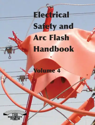
The Electrical Safety and Arc Flash Handbook, Vol. 4 provides comprehensive guidance on how to address the risks of electrical hazards and arc flashes in the workplace. Designed for electrical engineers, safety professionals, facility managers, and technicians, this volume focuses on the critical aspects of electrical safety, emphasizing the importance of risk assessments, hazard identification, and the implementation of safety measures to prevent arc flash accidents.
In this edition, we explore the fundamental principles of arc flash, including the science behind it, the causes, and the potential consequences. The handbook provides in-depth coverage of arc flash hazard analysis, helping professionals understand how to calculate and assess arc flash risks and establish safety protocols. It also discusses the role of protective equipment, proper labeling, and effective training programs to minimize the risk of arc flash incidents.
Volume 4 also includes updates on industry standards and regulations, offering practical insights on how to stay compliant with safety guidelines and improve overall workplace safety. Through case studies, best practices, and expert recommendations, this handbook empowers organizations to develop and implement comprehensive electrical safety programs that protect workers and ensure operational efficiency.
Latest Lineman Safety Articles
Testing Conditions and Guidelines for Personal Fall Protection Systems
Personal Fall Protection Systems mitigate falls via fall arrest and restraint using safety harnesses, lanyards, lifelines, and anchor points, supporting OSHA compliance, PPE best practices, and safe access on roofs, scaffolds, and elevated work platforms.
What Are Personal Fall Protection Systems?
Systems using harnesses, anchors, and lifelines to prevent or arrest falls and ensure OSHA-compliant worker safety.
✅ Components: full-body harness, lanyard, lifeline, connectors, anchors.
✅ Types: fall arrest, restraint, positioning, retrieval systems.
✅ Compliance: OSHA 1910/1926, ANSI Z359; inspection and training.
1. PERSONAL FALL ARREST SYSTEMS
(A) GENERAL TEST CONDITIONS
- Lifelines, lanyards, and deceleration devices should be attached to an anchorage and connected to the body-belt or body harness in the same manner as they would be when used to protect employees, except that lanyards should be tested only when connected directly to the anchorage, and not when connected to a lifeline.
- The anchorage should be rigid, and should not have a deflection greater than .04 inches (1 cm) when a force of 2,250 pounds (10.01 Kn) is applied.
- The frequency response of the load measuring instrumentation should be 100 Hz.
- The test weight used in the strength and force tests should be a rigid, metal cylindrical or torso-shaped object with a girth of 38 inches plus or minus 4 inches (96.5 cm plus or minus 10.16 cm).
- The lanyard or lifeline used to create the free fall distance should be the one supplied with the system, or in its absence, the least elastic lanyard or lifeline available to be used by the employee with the system.
- The test weight for each test should be hoisted to the required level and should be quickly released without having any appreciable motion imparted to it.
- The system’s performance should be evaluated, taking into account the range of environmental conditions for which it is designed to be used.
- Following the test, the system need not be capable of further operation.
For crews working at height, supplementary practices outlined in the fall protection for linemen resource can help align training with these general test conditions.
(B) STRENGTH TEST
- During the testing of all systems, a test weight of 300 pounds plus or minus 5 pounds (136.08 kg plus or minus 2.27 kg) should be used. (See paragraph (4) above.)
- The test consists of dropping the test weight once. A new unused system should be used for each test.
- For lanyard systems, the lanyard length should be 6 feet plus or minus 2 inches (1.83 m plus or minus 5.08 cm) as measured from the fixed anchorage to the attachment on the body belt or harness.
- For rope-grab-type deceleration systems, the length of the lifeline above the center line of the grabbing mechanism to the lifeline’s anchorage point should not exceed 2 feet (0.61 m).
- For lanyard systems, for systems with deceleration devices which do not automatically limit free fall distance to 2 feet (0.61 m) or less, and for systems with deceleration devices which have a connection distance in excess of 1 foot (0.31 m) (measured between the centerline of the lifeline and the attachment point to the body belt or harness), the test weight should be rigged to free fall a distance of 7.5 feet (2.29 m) from a point that is 1.5 feet (45.72 cm) above the anchorage point, to its hanging location (6 feet (1.83 m) below the anchorage). The test weight should fall without interference, obstruction, or hitting the floor or the ground during the test. In non-elastic wire lanyard of sufficient length may need to be added to the system (for test purposes) to create the necessary free fall distance.
- For deceleration device systems with integral lifelines or lanyards which automatically limit free fall distance to 2 feet (0.61 m) or less, the test weight should be rigged to free fall a distance of four feet (1.22 m).
- Any weight which detaches from the belt or harness should constitute failure for the strength test.
When planning documentation of these results, cross-referencing standardized methods from power cable test programs can improve traceability and record keeping.
Facilities that route conductors near test areas should secure them with cable cleats to reduce snag hazards around anchors and drop zones.
(C) FORCE TEST GENERAL. THE TEST CONSISTS OF DROPPING THE RESPECTIVE TEST
WEIGHT ONCE. A NEW, UNUSED SYSTEM SHOULD BE USED FOR EACH TEST
- For lanyard systems. (i) A test weight of 220 pounds plus or minus three pounds (99.79 kg plus or minus 1.36 kg) should be used (see paragraph (4) above). (ii) Lanyard length should be 6 feet plus or minus 2 inches (1.83 m plus or minus 5.08 cm) as measured from the fixed anchorage to the attachment on the body belt or body harness. (iii) The test weight should fall free from the anchorage level to its handling location (a total of 6 feet (1.83 m) free fall distance) without interference, obstruction, or hitting the floor or ground during the test.
- For all other systems. (i) A test weight of 220 pounds plus or minus 3 pounds (99.79 kg plus or minus 1.36 kg) should be used (see paragraph (4) above). (ii) The free fall distance to be used in the test should be the maximum fall distance physically permitted by the system during normal use conditions, up to a maximum free fall distance for the test weight of 6 feet (1.83 m), except as follows: (A) For deceleration systems which have a connection link or lanyard, the test weight should free fall a distance equal to the connection distance (measured between the center line of the lifeline and the attachment point to the body belt or harness). (B) For deceleration device systems with integral life lines or lanyards which automatically limit free fall distance to 2 feet (0.61 m) or less, the test weight should free fall a distance equal to that permitted by the system in normal use. (For example, to test a system with a self-retracting lifeline or lanyard, the test weight should be supported and the system allowed to retract the lifeline or lanyard as it would in normal use. The test weight would then be released and the force and deceleration distance measured.)
- Failure. A system fails the force test if the recorded maximum arresting force exceeds 1,260 pounds (5.6 Kn) when using a body belt, or exceeds 2,520 pounds (11.21 Kn) when using a body harness.
- Distances. The maximum elongation and decelerationdistance should be recorded during the force test.
Technicians should also review safe setup, handling, and verification practices detailed in cable handling and testing procedures to maintain consistency during force measurements.
Where electrical systems are present near test rigs, incorporating checks informed by line leakage testing guidelines can mitigate inadvertent shock exposure.
(D) DECELERATION DEVICE TESTS - GENERAL. THE DEVICE SHOULD BE EVALUATED
OR TESTED UNDER THE ENVIRONMENTAL CONDITIONS (SUCH AS RAIN, ICE,
GREASE, DIRT, TYPE OF LIFELINE, ETC.) FOR WHICH THE DEVICE IS DESIGNED
- Rope-grab-type deceleration devices. (i) Devices should be moved on a lifeline 1,000 times over the same length of line a distance of not less than 1 foot (30.48 cm), and the mechanism should lock each time. (ii) Unless the device is permanently marked to indicate thetype of lifelines which must be used, several types (different diameters and different materials) of lifelines should be used to test the device.
- Other-self-activating-type deceleration devices. The locking mechanisms of other self-activating-type deceleration devices designed for more than one arrest should lock each of 1,000 times as they would in normal service.
Because weather and transient overvoltage events can influence device performance, coordinating with lightning protection strategies supports safer operations during storms.
2. POSITIONING DEVICE SYSTEMS
(A) TEST CONDITIONS
- The fixed anchorage should be rigid and should not have a deflection greater than .04 inches (1.02 mm) when a force of 2,250 pounds (10.01 Kn) is applied.
- For lineman’s body belts and pole straps, the body belt should be secured to a 250 pound (113.4 kg) bag of sand at a point which simulates the waist of an employee. One end of the pole strap should be attached to the rigid anchorage and the other end to the body belt. The sand bag should be allowed to free fall a distance of 4 feet (1.22 m). Failure of the pole strap and body belt should be indicated by any breakage or slippage sufficient to permit the bag to fall free to the ground.
- For window cleaner’s belts, the complete belt should withstand a drop test consisting of a 250 pound (113.4 kg) weight falling free for a distance of 6 feet (1.83 m). The weight should be a rigid object with a girth of 38 inches plus or minus four inches (96.52 cm plus or minus 10.16 cm.) The weight should be placed in the waistband with the belt buckle drawn firmly against the weight, as when the belt is worn by a window cleaner. One belt terminal should be attached to a rigid anchor and the other terminal should hang free. The terminals should be adjusted to their maximum span. The weight fastened in the freely suspended belt should then be lifted exactly 6 feet (1.83 m) above its “at rest” position and released so as to permit a free fall of 6 feet (1.83 m) vertically below the point of attachment of the terminal anchor. The belt system should be equipped with devices and instrumentation capable of measuring the duration and magnitude of the arrest forces. Any breakage or slippage which permits the weight to fall free of the system constitutes failure of the test. In addition, the initial and subsequent arresting force peaks should be measured and should not exceed 2,000 pounds (8.9 Kn) for more than 2 milliseconds for the initial impact, nor exceed 1,000 pounds (4.45 Kn) for the remainder of the arrest time.
- All other positioning device systems (except for restraint line systems) should withstand a drop test consisting of a 250-pound (113.4 kg) weight falling free for a distance of 4 feet (1.22 m). The weight should be a rigid object with a girth of 38 inches plus or minus 4 inches (96.52 cm plus or minus 10.16 cm). The body belt or harness should be affixed to the test weight as it would be to an employee. The system should be connected to the rigid anchor in the manner that the system would be connected in normal use. The weight should be lifted exactly 4 feet (1.22 m) above its “at rest” position and released so as to permit a vertical free fall of 4 feet (1.22 m). Any breakage or slippage which permits the weight to fall free to the ground should constitute failure of the system.
In industrial settings, maintaining clear fall zones around trays and supports is aided by the disciplined installation of cable in cable trays practices that minimize clutter near anchors.
Related Articles
Keeping the Lineman and His Work Site Safe
Linemen and His Work Safe outlines OSHA compliance, PPE, fall protection, energized-line procedures, lockout/tagout, arc-flash mitigation, and hazard assessments to protect utility crews working on high-voltage distribution, transmission, and substations.
What Is Linemen and His Work Safe?
Safety framework for linemen covering OSHA compliance, PPE, fall protection, LOTO, and arc-flash risk control.
✅ Conduct job hazard analysis and tailboard briefings daily
✅ Use PPE: Class E helmets, rubber gloves, FR clothing, EH boots
✅ Apply OSHA 1910.269, fall arrest, equipotential bonding, LOTO
Line-construction contractors can do their best to train the management, offer safety training and equipment and trust the foremen who are appointed to a job, but it is an inherently dangerous business. Despite all the safeguards, some new linemen say this is what some foremen tell them about safety procedures: “That’s the way you may have learned it in training, but this is how it’s done on the job ...”
Training is designed to keep linemen safe. But is that training and equipment being put to proper use? The answer varies depending on the job and the foreman—more so than the company—according to linemen who have described the situation. Often even one company can be employing a variety of foremen with a variety of dedication to safety. For practical context, crews can review construction electrical safety resources to align field methods with training.
Contractors often find there are a lot of shortcuts being taken. Safety can vary widely within one company, especially if a foreman “develops” his own rules, perhaps to put productivity ahead of everything else. Guidance on responsibilities when working with power lines underscores why ad hoc rules jeopardize crews and the public.
Linemen learn the fundamentals in school, but training does not necessarily extend to the job site. Most contractors are highly committed to safety. They know that not only is it disastrous to have an injury or fatality because of lax safety, it is also financially calamitous. Many firms tighten procedures by using electrical safety program development guidance to bridge policy and practice.
The calculated risks that save lineworkers a few minutes on the job can quickly become a habit. For example, workers may fail to cover up equipment over energized lines or shore trench excavation to avoid cave-ins. Pre-job planning built around electrical safety work practices helps eliminate these shortcuts before exposure occurs.
The problem is persistent enough that NECA, IBEW and OSHA are seeking improvements. NECA has teamed up with IBEW, the Edison Electric Institute and some large line construction firms, to create the Transmission and Distribution Strategic Partnership to help improve lineman and foreman safety.
“It’s a fact of life that a lot of linemen work on live wires and equipment energized at tens of thousands of volts,” said Brooke Stauffer, NECA’s executive director of standards and safety and a leader in the partnership. He added that utility customers are rarely willing to shut down power for repairs. “The main problem is the giant feeders,” Stauffer said. “You can’t shut off a whole city.” For specialized environments, clarifying classifications through guidance on working in substations supports accurate hazard assessments and work clearances.
Despite these realities, as well as the need to get jobs done quickly, Stauffer said there are safe ways to work productively. “Effective supervision is important.”
Some contractors are in better position than others to regulate those jobs. L.E. Meyers, for instance, has a safety web of auditors and managers who evaluate each job.
“I don’t find it to be a problem,” said Todd Cooper, an L.E. Meyers regional manager. Their foremen, he said, generally have stayed with the company many years and are well trained and reliable. They are educated in essential safety and project-management skills, and put under the guidance of a construction manager. In addition, a job site safety review (JSSR) is filled out for each job. L.E. Meyers may be a model for good safety programs that keep management, foremen and linemen on the same page when it comes to safety.
“A big part of your success has to do with training,” Cooper said.
Training in all safety aspects, including grounding procedures, which Cooper cites as the biggest hazard, has given them some comfort with their own foremen. In addition, safety audits include safety supervisors, district managers, regional managers, district vice president, and vice president and manager of safety who visit the job site regularly to oversee the work.
Lee Boulanger, L.E. Meyers manager of safety operations, is responsible for ensuring the work site is as safe as possible. Boulanger points out that experience plays a key role in safety. “There’s a variety of experience out there,” he said. “When there’s a high-line job you can’t send someone out who doesn’t understand what needs to be done.”
But what about the companies that don’t have that degree of safety structure? Larger companies generally have a safety protocol that involves numerous safety representatives as well as safety audits and other forms to be filled out by foremen and project managers. Smaller companies may not have that luxury, and even the large companies can’t have someone on the job site every hour of every day. Ultimately, safety decisions are in the hands of the foreman on the job.
Smaller companies can benefit from the ability of management to make personal appearances at job sites. These kinds of visits are fairly common for many companies and are effective as well. There is no substitute for going to the workplace and seeing for yourself what is happening. Talking to employees frankly can often yield useful information as well. Every company can gain from taking a second look at its safety training program and safety procedures. Keeping a watchful eye over each job and each foreman, as well as polling the linemen can help contractors ensure that their crews are as safe as they can be.
There are signs of improvement throughout the industry as well. For one thing, the number of accidents has leveled. That may be in part due to better equipment and more rigorous training as well as OSHA standards. In addition, the attitudes of workers themselves may be changing. While they may have a reputation for being “tough guys” who aren’t afraid of “taking risks,” workers recently out of school are better educated in the value of following safety procedures. Accessible primers on electrical safety reinforce this shift with checklists, case studies, and task-specific controls.
In California, contractors are taking advantage of a foreman safety training course. However, not many linemen and foremen have the incentive to take the class. Armando Mendez, director of apprentice training for California/Nevada JATC, said they established a construction foreman safety-training course that was initially mandatory and involved the basics of pole climbing, equipment operation, working with primary voltage, and both overhead and underground safety. Since the program began in January 2003, about 450 linemen have attended. However, numbers have dwindled since the program became voluntary, partly because of lack of IBEW support for a mandatory program and because most contractors do not pay linemen to attend. In May, Mendez said, only two people turned out for the course. Broader access to electrical safety training can improve participation and retention of critical skills over time.
The 16-hour course offers training for linemen for two years of work, involving safety, responsibility of foremen, tool and equipment management and legal issues. The second portion of the course involves estimating and project management.
“We try to run it with 21 people, sometimes it is larger and sometimes smaller,” Mendez said. “It’s supposed to be on the journeyman’s own accord.
“In our business, one minute you’re a lineman, the next minute you’re a foreman. It’s like, ‘Here’s the pickup and the keys,’” Mendez said, noting that often those selections are not based on seniority and those with no basic training are at a disadvantage. “I’m hoping contractors will encourage their foremen to attend. It’s a big behavioral change for journeymen.”
According to Leo Jordan, director of safety for Pouk & Steinle in Riverside, Calif., most of his foremen have taken the safety training course. But one problem contractors face is the turnover of foremen and linemen and the quick appointment of foremen who may or may not have significant training.
“I am constantly discussing (the job) with the foreman,” Jordan said. “It has to start with the foreman.”
With each new job, review of what needs to be done and what equipment will be used takes place between management and foremen, before they then go to the linemen. Talking with the general foreman also helps give the contractor perspective on what is happening on the job site, but it’s not always a guaranteed source of information, either. Sometimes selection of a line foreman is a matter of “eenie meenie minie moe,” Jordan pointed out, and not all linemen are enthusiastic about being selected.
“It’s more paperwork, more responsibility and not that much more money,” Jordan said. “The solution is constantly talking with the foreman on down. Getting them to recognize the importance of safety and to say something when they see something wrong.”
Jordan added that many younger workers are raised in a more regulated environment. In addition, OSHA regulations and customer demand are forcing a close look at safety by contractors as well as the foremen and linemen themselves.
“There are a lot of factors to make you want to do better,” Jordan said. “The hazards have always been there. You can never stop thinking because the hazards can kill you.”
Michael Gilchrist, Northeastern Line Constructors Chapter manager, pointed out that “obviously in human nature some people are better than others…it’s to a contractor’s benefit to keep an eye out.” Gilchrist emphasized the importance of tailgate safety talks, in which the foreman lays out the details of the job with the crew.
At the Southeastern Line Constructors Chapter, similar issues take place. Manager Steve Gaines Jr. points out that linemen always work “in imminent threat of physical injury.” Once a lineman gets used to that threat, it is not a great stretch to imagine a sense of machismo that leads to inconsistent safety practices.
In many cases, Gaines said, it’s a matter of new blood coming from apprenticeship training replacing the more cavalier practices of the old school. In the meantime, the more experienced linemen are not likely to accept safety-related feedback from their junior crew members well.
The Southeastern Line Constructors Apprentice Training (SELCAT) has joined forces with NECA, IBEW Districts 5 and 10, and OSHA to seek training improvements and journeymen oversight. Implemented in September 2003, the alliance involves quarterly meetings with members to talk about training programs, meetings they have attended and related safety-training issues.
Gaines, who has spoken to each SELCAT class for the past four years, said some companies have excellent safety oversight, while others might not be as rigorous.
“Some companies are very much in touch,” he said. “They monitor all the projects and emphasize the tailgate safety sessions.”
For those who struggle to maintain safety consistency, the solution may not be simple, but inclusion of better training, management oversight and employment of younger, safety-conscious linemen will help take them in the right direction.
Related Articles
Fall Protection: The ABCs of Connecting Devices
Fall protection reduces fall hazards using harnesses, lifelines, guardrails, anchors, and PPE, supporting OSHA compliance, risk assessment, training, and safe work at height for construction, maintenance, and industrial operations and tasks.
What Is Fall Protection?
Fall protection uses systems and practices to prevent or arrest falls, ensuring OSHA-compliant safety for work at height.
✅ Select anchors, lifelines, and guardrails via risk assessment.
✅ Use full-body harness, lanyard, and connectors per OSHA.
✅ Train workers and inspect PPE and anchors before each shift.
A personal fall protection arrest system (PFAS) is comprised of three vital components: an anchorage, body wear (full-body harnesses), and a connecting device (a shock-absorbing lanyard or self-retracting lifeline). The safety of at-height workers depends on these three components, and each one must be in place and used properly to provide maximum worker protection.
When discussing fall protection, anchorage connectors and full body harnesses receive a lot of attention. We don’t always stop to think about connecting devices like self-retracting lifelines or shock-absorbing lanyards, and yet these are the two components that bear the greatest forces during a fall. For trade-specific guidance, see the personal fall protection systems practices used by utility line workers for additional context.
Before we discuss the importance of the connecting device, let’s review the definition of each PFAS component, as defined by OSHA and ANSI. When electrical tasks are involved, aligning PFAS planning with NFPA 70E arc flash label requirements helps ensure hazards are communicated before work begins.
According to OSHA, a personal fall arrest system is required if any risk exists that a worker may fall from an elevated position. Fall protection itself is required anytime a worker reaches a height of four or more feet for general industry and six or more feet for construction. To determine your working height, measure the distance from the walking/working surface to a lower level or the ground below. As we discussed above, OSHA mandates the use of a full-body harness with a shock-absorbing lanyard or retractable lifeline as part of the complete PFAS. A full-body harness, for instance, distributes the forces throughout the body, and a shock-absorbing lanyard decreases the total fall arresting forces. Let’s look at each of these components, briefly, before diving deeper into the importance and specifications of connecting devices such as shock-absorbing lanyards and self-retracting lifelines.
ANCHORAGE/ANCHORAGE CONNECTORS:
An anchorage is commonly referred to as a tie-off point, such as an I-beam, rebar, scaffolding, or rigid track system. An anchorage is—quite literally—a secure point of attachment for your lifeline/ lanyard that is independent from the worker’s means of support/suspension. An anchorage connector, on the other hand, is the component used to join the connecting device (shock absorbing lanyard or self-retracting lifeline) to the anchorage. Anchorages must be placed high enough for a worker to avoid contact with a lower level should a fall occur, and they should be able to support 5,000 pounds of force per worker or maintain a safety factor of at least two, under the supervision of a qualified person. Anchorage connectors must be positioned so that workers won’t endure a swing fall in the event of a fall from height.
FALL PROTECTION BODY WEAR:
Body wear is the personal fall protection equipment worn by a worker at height. A full-body harness is the only acceptable form of body wear for fall arrest applications. That’s because a full body harness distributes fall arrest forces across the shoulders, thighs, and pelvis. They also have a center back fall arrest attachment to connect to the fall arrest connecting device and may even include additional D-Rings for use in worker positioning, fall prevention, or suspension. Where electrical hazards are present, harness selection should also account for arc flash levels of protection so PPE categories and fall arrest gear work together.
Full-body harnesses must meet the requirements of ANSI/ASSE Z359.1 for fall arrest applications. This means that any work positioning or travel restraint attachments (D-Rings) must withstand a dynamic strength test of a 3.3-foot free fall using a 220-pound test weight. Additionally, the dorsal (back) D-Ring must be suitable for rescue applications unless otherwise prohibited by the manufacturer. Other rescue attachments must meet the 3,600-pound static load test criteria, along with the dynamic test criteria of a two-foot free-fall distance (also) using a 220-pound test weight. Coordinating harness features with arc flash safety gear helps maintain compliance across both fall and electrical risk profiles.
CONNECTING DEVICES:
Connecting fall protection devices are a crucial component of a complete PFAS. The connecting subsystem is the critical link that joins the full-body harness (body wear) to the anchorage/anchorage connector. Connecting devices can consist of energy-absorbing lanyards, self-retracting lifelines, rope grabs, or retrieval systems. How the connection is made depends on whether the worker is equipped for personal fall arrest or work positioning. For the sake of this discussion, we are only focusing on personal fall arrest components. In energized areas, material choices should be compatible with arc flash protection to avoid degraded performance from heat or molten metal.
The connecting means for a PFAS is usually either an energy absorbing lanyard or self-retracting lifeline. A lanyard is literally defined as a flexible line securing a full-body harness to an anchorage point. Energy absorbing lanyards reduce the energy transmitted to the user’s body in the event of a fall. Shock absorbing lanyards also provide deceleration distance during a fall. This reduces the fall-arresting forces on the worker by approximately 60-80 percent below the threshold of injury, as specified by OSHA and ANSI. OSHA mandates that all lanyards include double-action, self-closing, self-locking snap hooks to reduce the possibility of roll-out. Shock absorber packs can also be built into non-shock-absorbing lanyards to provide shock-absorbing capabilities. The inner core of a shock-absorbing pack expands smoothly to reduce fall arrest forces during a fall.
Self-retracting lifelines (SRL’s) are another viable option for connecting devices, depending on your application and fall protection needs. Self-retracting lifelines reduce the free-fall distance and energy loads from a fall. SRL’s also enable greater horizontal and vertical mobility than standard six-foot shock absorbing lanyards. There are great benefits to using SRL’s, including shorter activation and arresting distances, which reduce the risk of worker’s impacting the ground or lower level below. While standard shock absorbing lanyards allow for up to six feet of free-fall distance before activating, self-retracting lifelines require less than two feet to arrest free falls. Selecting SRLs and lanyards that do not interfere with required arc flash gear can improve mobility while preserving electrical PPE integrity.
According to OSHA 1926.502(d), horizontal lifelines must be designed with a minimum breaking strength of 5,000 pounds. Similarly, self-retracting lifelines and lanyards that do not limit the free fall distance to two feet or less must be capable of sustaining a minimum tensile load of 5,000 pounds when fully extended. However, self-retracting lifelines that automatically limit the free-fall distance to two feet or less must only be capable of sustaining a minimum tensile load of 3,000 pounds when fully extended.
Connecting fall protection devices offer many options, and they should be considered based on the application at hand and working environment. It’s always smart to use a lanyard or lifeline attached to an anchorage point that is positioned directly overhead to protect workers from swing fall. Although all three components of a PFAS are subjected to the total fall force, connecting devices are comprised of only one strength member (webbing, rope, steel cable, etc.). It’s essential to choose a connecting device that is high quality and to check it daily for excessive exposure to UV light, chemicals, physical damage, and/or improper storage. Inadequate inspection can easily lead to device failure. When planning work near energized equipment, verify that fall protection integrates with required arc flash safety equipment to prevent conflicting PPE requirements.
Consider the following when selecting the right type of fall protection connecting device for your specific personal fall arrest needs:
- Application and Environmental Conditions—this includes the presence of moisture, dirt, grease, oil, acids, hazards and obstructions, and ambient temperature.
- Potential Fall Distance—your potential fall distance is usually greater than anticipated. It’s important to consider the length of your connecting device, along with the length of elongation during deceleration, worker height, and an added safety factor.
- System Component Compatibility—It’s crucial to design test your PFAS as a complete system because components from multiple manufacturers may not be compatible with one another. Incompatible or non-interchangeable components can easily cause roll-out.
- Product Quality and Regulations—Don’t skimp on your PFAS components. The better the quality, the safer the worker will be. Furthermore, although OSHA fall protection regulations are enforced by a federal agency, ANSI standards are suggestive and self-enforced. Even so, ANSI standards should not be taken for granted. Use ANSI standards alongside OSHA regulations as part of a stated performance indicator. ANSI standards are written to save lives and prevent worker injury and should not be taken lightly.
Related Articles
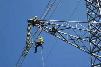
Electrical Lineman Safety Equipment - Tools of the Trade
Lineman safety equipment includes PPE, arc-flash gear, fall protection, insulated gloves, dielectric boots, hot sticks, rescue kits, grounding sets, and harnesses, engineered to OSHA and NFPA 70E standards for high-voltage electrical work.
What Is Lineman Safety Equipment?
Lineman safety equipment is PPE and gear mitigating electrical, arc-flash, and fall hazards on overhead line work.
✅ PPE: arc-rated clothing, class-rated gloves, dielectric boots
✅ Fall arrest: full-body harness, lanyards, SRLs per ANSI Z359
✅ Live-line tools: hot sticks, grounds, phasing meters, rescue kits
When working in close proximity to exposed energized equipment or working on live electrical circuits, it’s necessary to protect not only the equipment being worked on but also the worker. Rubber insulating gloves and insulated hand tools are vital components of a successful PPE system and should be used in conjunction with each other to provide the maximum protection for the worker.
It’s common to perform a task on de-energized equipment which is locked out and tagged out while still being within the shock boundary and in close proximity to other live equipment. In this case, a worker could accidentally lose control of a tool which could then make contact with live parts. If non-insulated hand tools were being used in this scenario, in addition to a shock hazard, it is very possible that a phase over would result and an arc flash would occur. Not only could the worker be exposed to injury, but the equipment in close vicinity to this incident could sustain serious damage resulting in costly repairs, replacement, or downtime. For a deeper overview of mitigation strategies, consult the arc flash protection guidance available today.
Tools with plastic coatings or plastic handles are not suitable when “live” circuits are close to the task at hand. Employees should only consider the use of insulated tools that are marked with the official international “Suitable for live working” symbol for any type of work in close proximity to energized equipment. Complementary PPE selections are outlined in the arc flash safety gear recommendations for technicians.
The double-triangle marking is the international symbol used to identify tools as safe for energized work. This symbol must be marked on all truly insulated hand tools. These insulated hand tools have a maximum use rating of 1,000VAC and are dielectrically tested at 10,000VAC; this equates to a safety margin factor of 10. These tools should meet current ASTM F1505 and IEC 60903 standards for insulated hand tools and useful for compliance with the CSA Z462-15 standard. While insulating hand tools are designed foremost to offer shock protection for the worker, they are still considered secondary protection. Use of recognized safe work methods and other PPE should not be ignored. Understanding category thresholds is simplified in the arc flash levels of protection overview for planning.
Maintenance
Use and maintenance of insulated tools are beyond the scope of the existing standards and specifications. You should use insulated tools for their intended applications only; for example, screwdrivers should not be used to pry or chisel. You should never modify or alter a tool from its original design. For instance, cutting back the insulation on a socket for use in tight spaces could in fact expose the worker to injury. When establishing shop protocols, review the procedures to protect against electrocution to reinforce correct practices.
Because moisture, films, or other surface contaminants are conductive, insulated tools must be kept clean, dry, and free of any surface contaminants. The cleaning of insulated tools can be accomplished by using the same specialty concentrated detergent used to remove oils, grease and dirt from rubber insulated gloves. The important thing to remember when using cleaning agents is to ensure the agent does not contain any chemicals which may harm or lessen the protective value of the insulating coating. The ultimate goal is getting a residue free surface after cleaning and maintaining the insulation integrity of the tool. The same care principles used for insulating rubber gloves apply to tool insulation maintenance.
Insulated hand tools should be stored properly to minimize risk of damage to the insulation. Avoid storing in proximity to sources of heat such as radiators, furnaces, and steam pipes. Organized storage with rated barriers is also highlighted in the arc flash safety equipment guidance for facilities.
Inspection
The barrier material used to produce insulating tools is impact resistant and flame retardant and there is no re-certification process for insulated tools. Inspect all tools before use and discard tools that show any signs of visible damage. The ASTM F1505 standard allows for both single and double layer coatings. If double layer coatings are used, they should be of contrasting colours. For broader risk controls, explore advanced protection against electromagnetic exposures and electric arc strategies that complement tool inspection.
Overlapping two-colour insulated tools make inspection easier which adds to overall safety. If the under layer colour is showing through the over layer colour, the tool is no longer considered properly insulated and should be replaced. While there is no specific requirement in regards to colour other than the layers being contrasting, the industry has adopted the use of orange for the outer layer and yellow for the inner layer for all-purpose tools. Most manufacturers producing double layer insulated tools follow this colour pattern thus allowing the inner layer to be seen during the tool inspection process. Note that specialty tools made from Aluminum-Bronze and Copper-Beryllium alloys that are non-sparking and non-magnetic and are insulated, will also have a colour-contrasting double layer coating. To differentiate from all-purpose tools, these specialty tools use another colour for the outer insulating layer.
For safety reasons other than shock and arc flash hazards, it is recommended that appropriate eye and hand protection be worn when using any type of hand tool. To fully comply with the CSA Z462-15 standard, truly insulated hand tools should be used if there is any chance that the tool will make contact with an energized source. A complete insulated tool program meeting these standards is achievable; you simply need to ensure that all your tools meet the ASTM F1505 and/or IEC 60903 standards for insulated hand tools.
Injection Molded Insulated Tools
Injection molded tools are another type of insulated tool in the market. Injection molded means they are not PVC dipped so therefore will not have a double layer coating. However, they have the same insulating properties and are also a great insulated tool
Related Articles
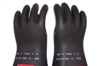
Hand Safety - Protective Gloves
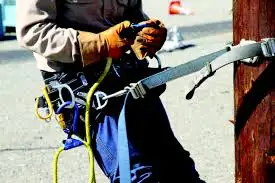
Insulating rubber gloves protect electricians from shock with dielectric PPE, ASTM/IEC class ratings, arc-flash compatibility, and OSHA compliance, enabling safe high-voltage maintenance, live-line work, and substation testing when paired with leather protectors and regular recertification.
What Are Insulating Rubber Gloves?
Dielectric PPE gloves rated by class to prevent electrical shock during high-voltage work and testing.
✅ Rated Class 00–4 per ASTM D120; inspect, air test, and date-stamp.
✅ Use with leather protectors; store cuff-up in ventilated bags.
✅ Re-test every 6 months; keep dry, clean, and away from hydrocarbons.
Rubber insulating gloves are among the most important articles of personal protection for electrical workers. To be effective, the gloves must incorporate high dielectric and physical strength, along with flexibility and durability. For superior performance they should meet and/or exceed the requirements of current American Society for Testing and Materials (ASTM) D120 specifications. Gloves should also be electrically tested following ASTM D120/IEC903 specifications.
A glove system usually consists of:
Rubber Insulating Gloves: Classified by the level of voltageand protection they provide.
Liner Gloves: Are used to reduce the discomfort of wearing rubber insulating gloves in all seasons, for year round use.
Liners: provide warmth in cold weather, while they absorb perspiration in the warm months. These can have a straight cuff or knit wrist.
Leather Protector Gloves: Should always be worn over rubber insulating gloves to provide the mechanical protection needed against cuts, abrasions and punctures. Look for those that are steam pressed on curved hand forms to ensure proper fit over rubber gloves. For a broader overview of compatible personal protective equipment, see the guidance on lineman safety equipment to ensure system-level protection.
ELECTRICAL-PROTECTIVE GLOVE CLASSIFICATION
Employees who work in close proximity to live electrical current may require a variety of electrically insulating protective equipment. The Occupational Safety and Health Administration (OSHA) outlines this in their Electrical Protective Equipment Standard (29 CFR 1910.137) which provides the design requirements and in-service care and use requirements for electricalinsulating gloves and sleeves as well as insulating blankets, matting,
covers and line hoses. Electrical-protective gloves are categorized by the level of voltage protection they provide and whether or not they’re resistant to ozone. Voltage protection is broken down into the following classes: Because electrical work often also involves arc-flash hazards, practitioners should review advanced protection measures against electromagnetic exposures and electric arc to align gloves with a coordinated PPE plan.
For gloves, ozone resistance is covered by the “Type” designation. A Type I glove is not ozone-resistant, while a Type II is ozone-resistant. Once the gloves have been issued, OSHA requires that “protective equipment shall be maintained in a safe, reliable condition”. This requires that gloves be inspected for any damage before each day’s use. Gloves must also be inspected immediately following any incident that may have caused damage. OSHA requires that insulating gloves be given an air test along with the inspection. For program planning, a concise overview of electrical testing methods and best practices can help define inspection intervals and documentation.
OSHA requires air testing, but doesn’t explain how to perform the test. The test method is described in ASTM F 496, Specification for In-Service Care of Insulating Gloves and Sleeves. Basically, the glove is filled with air, either manually or by an inflator, and then checked for leakage. The leakage is detected by either listening for escaping air or holding the glove against the tester’s cheek to feel air releasing. Beyond air checks, understanding the principles of an electrical insulation resistance test can inform decisions about when to escalate to laboratory diagnostics.
As stated in ASTM specifications for In-Service Care and Use of Rubber Gloves and Sleeves, gloves and sleeves should be expanded no more than 1.5 times their normal size for type I, and 1.25 times normal for type II during the air test. The procedure should then be repeated with the glove turned inside out. In addition to this daily testing, OSHA requires “Electrical protective equipment shall be subjected to periodic electrical tests.” OSHA does not elaborate on a time frame for these tests, but ASTM F 496 does provide direction. It states that gloves being used in the field must be electrically retested every six months. When deeper diagnostics are warranted, selecting an appropriate insulation resistance tester ensures measurements are reliable and traceable.
Gloves that have not been placed into service after an electrical test shall not be placed into service unless they have been electrically tested within the previous 12 months. See reference below for Testing Agency information. OSHA recognizes that gloves meeting ASTM D 120-87, Specification for Rubber Insulating Gloves, and ASTM F 496, Specification for In-Service Care of Insulating Gloves and Sleeves, meet their requirements. Facilities may also standardize procedures for checking insulation resistance to complement scheduled retesting.
INSPECTION
In order to maintain the highest level of insulating protectionand ensure long life, it is essential that gloves (and sleeves) are properly cared for and stored.
Before each use, gloves and sleeves should be inspected for holes, rips or tears, ozone cutting, UV checking and signs of chemical deterioration. Refer to ASTM F 1236, Standard Guide for Visual Inspection of Electrical Protective Rubber Products for Additional Information.
Gloves and Sleeves should also be examined to determine if they show any damage as a result of chemical contamination, particularly from petroleum products. The first sign of exposure is swelling in the area of contamination. Should any rubber equipment be exposed to chemical contaminants or be suspect of any other physical damage, it should be turned in for inspection, cleaning and electrical testing.
Since sleeves cannot be inflated, they are inspected along the edge as they are rolled. Rolling will stretch the sleeve along the edge, making cuts, tears and ozone cutting more visible. After the outside of the sleeve is inspected, the procedure should also be repeated with the sleeve turned inside out.
COMMONLY ASKED QUESTIONS
Q. Can I just use the rubber glove only, and not have to buy the leather part?
A. Leather protective gloves should always be worn over rubber insulating gloves to provide the needed mechanical protection against cuts, abrasions, and punctures. For tasks with arc-flash exposure, consult current guidance on arc-flash clothing for electricians so glove selection integrates with garment ATPV ratings.
Q. Would re-testing be needed if I don’t use the gloves very often and visually see no damage?
A. Yes, re-testing is still needed to verify the integrity of the material and to ensure electrical safety is maintained for the user.
Q. If I find a hole, can I just “patch it” - like a tire inner tube?
A. No - because this would not comply with ASTM or OSHA Standards for Electrical Protective Gloves, and it would not pass Accredited Laboratory Testing.
From: Electrical Safety & Arc Flash Handbook Handbook, Volume 3, The Electricity Forum
Related Articles
Lineman Safety Media
Lineman Safety Articles From ET Magazine
Why Net-Zero is Cheaper for the UK
The United Kingdom has set an ambitious target to achieve net-zero greenhouse gas emissions by 2050. This goal necessitates a comprehensive transformation of various sectors, including energy, transportation, and agriculture. While the environmental imperatives are clear, there is growing evidence that this transition could also yield significant economic advantages for the nation.
Energy Sector Transformation
A pivotal component of the UK's net-zero strategy involves a substantial shift towards renewable energy sources. By 2040, projections suggest that wind and solar power will supply approximately 80% of the country's electricity needs. This transition is expected to reduce energy imports, enhancing national energy security and potentially lowering energy costs for consumers.
The adoption of technologies such as heat pumps for home heating is another crucial step. Heat pumps, which extract heat from the environment to warm homes, offer efficiencies of up to 400%. Their widespread adoption could lead to reduced reliance on fossil fuels and lower household energy bills.
Transportation Sector Overhaul
The automotive landscape is also undergoing significant changes. The Climate Change Committee (CCC) recommends that by 2040, 80% of cars on UK roads should be fully electric. This shift would decrease the demand for imported oil, enhance air quality, and align with global trends towards sustainable transportation.
Agricultural Adjustments
Agriculture plays a role in the nation's carbon footprint, particularly concerning meat consumption. The CCC advises that reducing meat consumption by approximately 260 grams per week per person could significantly lower emissions. This dietary shift would not only contribute to climate goals but also improve public health outcomes.
Economic Growth and Job Creation
The transition to a low-carbon economy is poised to stimulate economic growth through job creation and innovation. Investments in renewable energy infrastructure, such as solar panels and wind turbines, are expected to generate employment opportunities across various regions. For instance, in 2024, the installation of certified heat pumps, solar panels, and battery storage systems reached a record high, indicating a burgeoning green jobs sector.
Moreover, enhancing building insulation and adopting energy-efficient technologies can lead to substantial energy savings. These improvements not only reduce carbon emissions but also lower heating costs for households, thereby increasing disposable income and economic well-being.
Health and Social Benefits
Beyond economic and environmental gains, the net-zero transition offers significant health benefits. Upgrading homes with advanced insulation and modern heating systems can improve indoor air quality, reducing respiratory ailments and other health issues. Additionally, promoting active transportation methods, such as walking and cycling, can lead to healthier lifestyles and reduced public health expenditures.
Ensuring a Just Transition
To maintain public support for net-zero initiatives, it is crucial to distribute the costs and benefits equitably. Government policies should focus on making green technologies accessible and affordable, particularly for lower-income households. This approach ensures that the transition does not disproportionately burden vulnerable communities and that the economic benefits are widely shared.
Achieving net-zero emissions by 2050 presents both challenges and opportunities for the UK. The transition to renewable energy, sustainable transportation, and dietary changes offers the potential for economic growth, job creation, and improved public health. By implementing inclusive and forward-thinking policies, the UK can lead the way in demonstrating that environmental sustainability and economic prosperity are not mutually exclusive but mutually reinforcing
12 Tips to Protect Against Common Lineworker Safety Hazards
Lineworkers face numerous risks daily, from respiratory ailments to electrical hazards. These dangers can result in severe injuries, low blood pressure, bleeding, and vomiting. However, by adhering to established safety protocols, contractors and employers can significantly reduce the likelihood of accidents. Below are 12 practical tips to protect lineworkers from common safety hazards.
1. Identifying Job Hazards
The first step to mitigating risks is recognizing them. Conduct regular inspections of the worksite to identify potential hazards. Evaluate equipment and work conditions to detect safety threats that may be difficult to eliminate. Interview workers and managers to understand their concerns and observations. Use this feedback to create a detailed hazard map, marking both existing and potential hazards.
Involving workers in this process fosters a culture of safety and boosts morale. It’s crucial to maintain electrical installations, repair faulty appliances, and ensure the proper use of high-quality footwear. By addressing these concerns, employers create a safer working environment.
2. Using personal protective equipment
PPE is essential for protecting workers from injuries, infections, and other workplace hazards. Lineworkers should wear safety goggles, face shields, gas masks, and self-contained breathing apparatuses to guard against chemical splashes, burns, and respiratory diseases.
Ensure that all PPE complies with safety standards. Goggles and face shields should be free of cracks, and hard hats must be dent-free and stored away from high heat to maintain shell integrity. Workers should also wear high-visibility, heat-resistant overalls and gloves to protect against extreme temperatures and toxic substances.
3. Properly using cover-up equipment
Cover-up equipment shields lineworkers from energized machines and electrical currents. Items like line hoses and conductor covers prevent accidental contact with live conductors, thereby reducing the risk of electric shocks and arc flash hazards.
To maximize protection, ensure that workers have access to appropriate cover-up equipment. Regularly inspect and maintain these tools to ensure they remain in optimal working condition.
4. Protecting against currents in grounded systems
Grounded systems are often perceived as safe, but they can still pose risks due to electromagnetic fields. Under extreme conditions, these fields may create currents that endanger lineworkers.
To prevent such hazards, regularly inspect all equipment before use. Conduct safety training to educate workers about these hidden dangers and establish protocols for handling grounded systems safely.
Virtual Power Plants (Vpp) And Smart Grids: Integrating Renewable Energy For A Sustainable Future
The rapid shift toward renewable energy resources (RERs) has placed significant demands on traditional power systems. To address these challenges, modern energy infrastructure is evolving into smart grids, leveraging advanced technologies like Virtual Power Plants (VPPs) to enhance grid flexibility, reliability, and efficiency. A VPP is a collection of distributed energy resources (DERs), such as renewable energy sources, battery storage, controllable loads, and electric vehicles (EVs), that operate as a unified power plant through intelligent control and communication networks. By integrating VPPs with smart grids, the energy sector can better coordinate energy generation, storage, and consumption, facilitating a more resilient and efficient power network.
The Role of Virtual Power Plants in Smart Grids
VPPs function as dynamic and intelligent hubs within a smart grid. They utilize distributed intelligence to monitor, control, and optimize energy flows across multiple DERs. Unlike traditional power plants, which generate power at a central location, VPPs pool energy from multiple decentralized sources. This approach enhances grid stability, reduces reliance on fossil fuels, and improves the system’s ability to handle intermittent renewable energy sources such as wind and solar power.
One of the primary objectives of a VPP is to supply auxiliary services to the grid. This includes frequency regulation, voltage control, and reactive power support, all of which are essential for maintaining grid stability. By doing so, VPPs enable a smooth transition from a conventional grid to a smart grid, where communication and real-time control play critical roles. The integration of VPPs into smart grids introduces two distinct components: the Technical Virtual Power Plant (TVPP) and the Commercial Virtual Power Plant (CVPP).
The TVPP addresses technical aspects such as system security, operational constraints, and physical grid limitations. It ensures safe and stable grid operation by monitoring and controlling DERs in response to grid conditions. On the other hand, the CVPP focuses on the commercial dimension, optimizing the supply, pricing, and utilization of distributed energy resources for market-based transactions. By coordinating the two components, VPPs support a robust and intelligent power infrastructure.
Benefits of VPP-Integrated Smart Grids
Integrating VPPs into smart grids provides numerous benefits, particularly in improving the efficiency, reliability, and sustainability of energy systems. Key advantages include:
Enhanced Grid Flexibility: VPPs enable smart grids to dynamically respond to fluctuations in energy supply and demand. The ability to shift loads, store excess energy, and optimize energy dispatch allows for better grid flexibility, which is essential for handling the variability of renewable energy.
Optimal Use of Renewable Energy: By aggregating and coordinating distributed renewable energy sources, VPPs ensure maximum utilization of green energy. This reduces curtailment and minimizes energy wastage.
Improved Energy Efficiency: VPPs promote the optimal use of energy storage systems, reducing the need for expensive peaking power plants. Energy storage devices such as battery systems can store excess renewable energy during low-demand periods and discharge it during peak demand.
Reduction in Grid Congestion: By intelligently managing power flows, VPPs alleviate congestion on transmission and distribution networks. This reduces the likelihood of overloading grid components and avoids costly grid upgrades.
Market Participation and Revenue Streams: VPPs facilitate the participation of DERs in energy markets, allowing prosumers and small energy generators to sell surplus power. This creates new revenue streams and incentives for investing in renewable energy projects.
Decentralized Grid Management: Instead of relying on centralized control, smart grids with VPPs operate as a decentralized system. This enhances system resilience, reduces the risk of large-scale outages, and promotes local energy self-sufficiency.
Read full article in the Smart Grid & Linemen Safety Special Edition magazine
How Dangerous is Linemen Work?
Many occupations pose risks to workers, but few match the dangers that linemen face daily. Linemen play a critical role in maintaining and restoring the power grid, often working in extreme weather conditions, at significant heights, and around high-voltage electrical systems. Their work is essential to modern life, yet it comes with life-threatening hazards.
Statistics highlight the dangers of lineman work. The fatality rate for lineworkers is nearly four times higher than the national average for all occupations. Each year, an average of 26 linemen lose their lives due to work-related injuries. Additionally, linemen experience a non-fatal injury rate of 104.6 per 10,000 full-time workers. For every fatality, there are roughly 20 non-fatal injuries. Most of these incidents are linked to transportation-related accidents, falls, and electrical hazards.
The risks associated with the job have contributed to high turnover rates in the utility industry. Many experienced utility workers are retiring, and others are moving into roles in emerging technology sectors. For those who stay, the physical demands and daily risks can take a toll on mental and physical well-being.
The Hazards Linemen Face Every Day
In the early days of the utility industry, nearly one in four linemen died from work-related accidents. While safety standards and technology have significantly improved since then, linemen still face substantial risks. Advances such as flame-resistant clothing, rubber-insulated gloves, and digital tracking of energized equipment have enhanced worker protection. However, certain hazards remain unavoidable.
Electrocution
The leading cause of death among linemen is electrocution. Linemen work directly with high-voltage power lines, where even a single misstep can result in a fatal shock. Protective equipment, such as rubber gloves and line blankets, reduces risk, but accidents still occur, especially during storm-related emergency repairs.
Falls from Heights
Working at heights is a routine part of a lineman’s job. Lineworkers must climb poles or operate from aerial lifts, sometimes hundreds of feet above the ground. Falls account for 21% of lineman fatalities. Equipment malfunctions, loss of balance, or adverse weather can all lead to dangerous falls.
Read full article in the Smart Grid & Linemen Safety Special Edition magazine
Sign Up for Electricity Forum’s Lineman Safety Newsletter
Stay informed with our FREE Lineman Safety Newsletter — get the latest news, breakthrough technologies, and expert insights, delivered straight to your inbox.
Electricity Today T&D Magazine Subscribe for FREE
- Timely insights from industry experts
- Practical solutions T&D engineers
- Free access to every issue