Transmission & Distribution
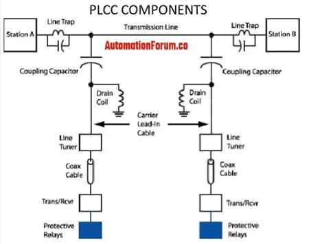
Power Line Carrier Communication Explained
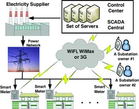
Power line carrier communication enables data transmission over electrical power lines for grid automation, SCADA telemetry, and protective relaying, using coupling capacitors, line traps, and narrowband modulation to support substation monitoring and smart grid control.
Applications of Power Line Carrier Communication in Modern Power Systems
Power line carrier communication (PLCC) is a vital technology for electrical professionals to understand in today's evolving energy landscape. By utilizing existing power lines for data transmission, PLCC offers a cost-effective and reliable communication solution for a wide range of applications within industrial, commercial, and institutional power systems. In transmission engineering contexts, PLCC must…
View more
Test Your Knowledge About Software and Apps!
Think you know Software and Apps? Take our quick, interactive quiz and test your knowledge in minutes.
- Instantly see your results and score
- Identify strengths and areas for improvement
- Challenge yourself on real-world electrical topics
Latest T&D Content

IEEE Transactions on Smart Grid
IEEE Transactions on Smart Grid publishes peer reviewed research that defines the technical boundaries for automation, DER coordination, cybersecurity, and resilience in modern utility systems. Its influence extends beyond academic discourse, shaping how grid operators evaluate state estimation accuracy, distributed control limits, and system risk under high penetration of inverter based resources.
For utility engineers and system operators, the journal marks the transition from conceptual innovation to deployable operational frameworks. Research published in IEEE Transactions on Smart Grid frequently informs how utilities interpret telemetry confidence, automation risk, and performance tolerance under stressed network conditions.
Unlike broad industry commentary, the journal…
View more
Transformer vs Autotransformer in Power Systems
Transformer vs Autotransformer compares isolation, winding design, voltage regulation, efficiency, cost, and safety for power distribution, step-up/step-down applications, helping engineers select the right device for load matching and reliable electrical performance.
Transformer vs. Autotransformer Explained
Transformers and autotransformers are essential components in the world of electrical engineering, playing a pivotal role in power distribution and voltage regulation. While both serve similar functions in transferring electrical energy efficiently, they differ significantly in design, operation, and application. Understanding the differences between transformers and autotransformers is crucial for selecting the right equipment in utility applications, where efficiency, cost, and performance are key…
View more
Oil Filled Transformer Explained
Oil filled transformer uses dielectric oil for insulation and cooling in distribution and substation applications, managing high voltage efficiently with robust thermal management and reliable power transformer performance for grid reliability and load stability.
Oil-Filled Transformer Explained: What You Need to Know
Oil filled transformers play a crucial role in the world of utility voltage converters, serving as the backbone of efficient power distribution systems. These transformers, filled with insulating liquid, are designed to filled and dry type transformers and ensure the safe and reliable transfer of electricity across vast networks. The liquid not only provides insulation but also…
View more
What is an Autotransformer Explained
What is an autotransformer? A single-winding transformer for AC power distribution, providing efficient step-up/step-down voltage regulation via taps, reduced copper losses, compact design, and adjustable output for motor starting and grid voltage stabilization.
What Is an Autotransformer?
An autotransformer is an electrical transformer with only one winding that acts as both the primary and secondary winding. Unlike traditional transformers with separate windings, an autotransformer uses a single coil acting as both the input and output, depending on the tapped point. This single winding structure allows for significant material savings, notably the savings of copper in an autotransformer, which can…
View more
What is a Stackable Energy Storage System?
Stackable energy storage system delivering modular lithium-ion battery modules with advanced BMS, inverter integration, and scalable capacity for microgrids, solar-plus-storage, peak shaving, load shifting, and UPS backup in residential, commercial, and industrial applications.
Stackable Energy Storage System Explained
A stackable energy storage system (SESS) offers a flexible and scalable solution for renewable energy storage. The modular design allows for easy expansion, and smart grid technology ensures the system operates at peak efficiency. By using a SESS in conjunction with distributed energy resources, it is possible to create a more resilient and reliable electrical grid. For broader context on grid…
View more
Three Phase Transformer Connections
Three Phase Transformer Connections configure windings in delta or wye to optimize voltage transformation, load balancing, and system reliability in power distribution networks.
Three-Phase Transformer Connections Explained
Why Three Phase Transformers Are Preferred
Large blocks of AC power are transmitted and distributed at high voltage levels through three-phase transformer connections. While it’s possible to connect three single-phase transformers to form a three-phase transformer bank, the standard approach is to integrate all three phase windings into a single core. This single-unit design offers:
Higher efficiency compared to three separate single-phase units.
Simpler busbar, switchgear, and wiring arrangements.
Reduced weight and…
View more
Substation Protection and Fault Containment Decisions
Substation protection defines how a power system behaves when faults occur, whether failures are isolated safely or escalate into equipment damage and outages. Its purpose is to control fault limits, response speed, and isolation boundaries so the grid survives worst-case events.
Substation protection is not a compliance exercise or a checklist of relays and breakers. It is a consequence-driven protection philosophy that determines how faults are interpreted, how aggressively they are cleared, and how far their effects are allowed to spread. When those decisions are misaligned with real system conditions, substations do not degrade gradually; they fail abruptly, often exceeding…
View more
T&D News
T&D Media

T&D Articles From ET Magazine

The Mentoring Gap: How the Loss of Informal Knowledge Is Affecting Safety
For much of the trade’s history, the most important safety lessons in line work were never written down. They were learned by proximity. New linemen watched how experienced hands approached a pole, handled a tool, or reacted when conditions changed. They learned when to slow down, when to stop talking, and when something simply did not feel right. These lessons were rarely formalized, yet they shaped judgment in ways no procedure ever could.
That informal transfer of knowledge is fading, and its absence is beginning to show.
The structure of the trade has changed rapidly. Accelerated retirements have removed decades…
View more
Grounding Assumptions: Where Line Crews Still Get Hurt Despite “Doing It Right”
Why Grounding Remains a Source of Serious Injury
Grounding is one of the most emphasized safety practices in line work, yet serious incidents continue to occur during grounded operations. These events rarely result from a lack of training or awareness. Instead, they stem from assumptions about how grounding behaves under real-world conditions that are more complex than any classroom scenario.
The Difference Between Training Scenarios and Field Reality
Training often presents grounding in controlled, idealized conditions. In the field, soil resistivity varies, access is limited, and system configurations change without warning. Temporary grounds are installed under time pressure, sometimes…
View more
The Near-Miss Problem: Why Utilities Collect Data but Crews Do Not Trust It
The Promise of Learning Before Someone Gets Hurt
Near-miss reporting is widely promoted as a cornerstone of modern safety management. In theory, it allows organizations to identify hazards, weak signals, and system failures before they result in injury or death. A near miss is a warning shot, an opportunity to learn without paying the highest price. Yet in many utilities, near-miss systems collect far less information than they could, not because incidents are rare, but because crews choose not to report them.
Why Silence Feels Safer Than Speaking Up
Linemen rarely avoid reporting near misses out of indifference. More often,…
View more
Human Factors on the Line: Fatigue, Complacency, and Decision Making at Height
How Real Incidents Actually Take Shape
Most serious line incidents do not begin with a dramatic failure or an obvious violation of rules. They begin quietly, through a sequence of small decisions made under ordinary pressure. A grip adjusted instead of reset. A stance accepted instead of corrected. A task continued rather than paused. None of these choices feel unsafe in the moment. In fact, they often feel efficient, reasonable, and consistent with experience. Yet when work is performed at height, these small decisions compound quickly, narrowing margins that cannot be recovered once something goes wrong.
Understanding how those decisions…
View more
FREE EF Electrical Training Catalog
Download our FREE Electrical Training Catalog and explore a full range of expert-led electrical training courses.

- Live online and in-person courses available
- Real-time instruction with Q&A from industry experts
- Flexible scheduling for your convenience
Sign Up for Electricity Forum’s Software and Apps Newsletter
Stay informed with our FREE Software and Apps Newsletter — get the latest news, breakthrough technologies, and expert insights, delivered straight to your inbox.