Transformer Protection
By Howard Williams, Technical Editor
By Howard Williams, Technical Editor

Our customized live online or in‑person group training can be delivered to your staff at your location.

Transformer protection safeguards transformers from faults, overloads, and electrical failures using relays, circuit breakers, and monitoring systems to ensure reliable operation.
Short Circuit Study & Protective Device Coordination
Arc Flash Analysis/Study - IEEE 1584 Update
Transformers are protected mostly against internal faults and external overloads. The type of isolation used should minimize disconnection time during faults and reduce the risk of catastrophic failure. Extended operation under abnormal conditions—such as overloads or internal faults—compromises equipment life, underscoring the need for prompt, coordinated protection. For a comprehensive foundation in system protection, visit our Power System Protection overview, which covers protective schemes and coordination methods.
A transformer may face overcurrents ranging from just above the rated capacity to 10–20 times the nameplate rating. Overloads typically produce lower current levels, whereas system faults cause high-current surges. Sustained overcurrents can cause:
Mechanical damage, including coil deformation or insulation failure from electromagnetic forces
Thermal damage due to prolonged heating and thermal overload
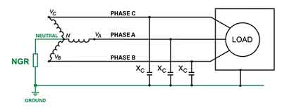
In all cases, the duration of overcurrent significantly impacts the extent of damage and increases the likelihood of through-fault current stresses. Protection coordination depends heavily on proper grounding transformer methods to ensure accurate fault detection.
Fluxing protection is essential in modern transformer design to prevent damage from excessive flux density in the core. When flux levels exceed the core’s saturation point, overheating and distortion can occur, affecting both efficiency and reliability. To mitigate this, static devices are often employed to regulate voltage and magnetic flux, maintaining optimal operating conditions. Without proper flux control, overfluxing can lead to core saturation and, in severe cases, structural stress on the transformer tank, resulting in insulation failure or mechanical deformation. Implementing reliable fluxing protection helps safeguard both the internal and external components of the transformer.
Download our FREE Electrical Training Catalog and explore a full range of expert-led electrical training courses.

Effective transformer protection depends on identifying various failure modes and applying appropriate protective devices. Below are the most commonly used schemes:
This method compares the current entering and leaving the transformer. A significant difference suggests an internal fault. It is one of the most sensitive and widely used isolation methods for medium- and large-power transformers and operates via a differential relay that detects unbalanced current flow.
Protects against excessive current caused by system overloads or faults. It uses inverse time relays or fuses to trip when current exceeds preset limits for a specified duration. Modern overcurrent disconnection ensures transformers are quickly isolated from faulted sections.
Detects earth faults by measuring unbalanced currents in the transformer winding. It prevents damage caused by insulation failure or partial winding breakdown and is often coordinated with system grounding schemes.
Installed on oil-filled transformers, the Buchholz relay detects gas accumulation and oil movement caused by internal faults. It provides early warning and tripping in case of severe issues.
Monitors winding and oil temperatures. Excessive heat from prolonged loading or ventilation failure can degrade insulation and lead to failure, triggering alarms or a shutdown.
Protects against sudden increases in internal pressure caused by arcing or internal short circuits. These devices vent excess pressure to avoid tank rupture and prevent catastrophic failure.
Understanding the role of relays is essential—explore how different protective relay types and multifunction relays help detect faults and initiate circuit isolation.
Whatever the cause or duration of overcurrent, it is essential that protective devices detect the issue and isolate the equipment quickly. Two common types are:
Fuses: Used for smaller transformers (up to 5000–10,000 kVA), fuses contain a fusible link that melts during sustained overcurrents, disconnecting the unit.
Protective Relays: These electromagnetic or digital devices detect abnormal current levels via CTs (current transformers) and activate circuit breakers. Relays are standard for medium and large power transformers.
For deeper insight into the devices involved, check out our articles on what is a fuse and circuit breaker types, both vital to transformer protection strategies.
Every protective device has a time-current operating characteristic that must be coordinated with transformer capabilities. According to ANSI/IEEE C57, transformer capability curves define both:
Thermal limits (curve A)
Mechanical limits (curve B, based on impedance)
To avoid damage, transformer protection relay curves must fall below both limits on coordination charts. This ensures reliable isolation during through-fault current and overloads. Coordinating fuses and breakers with limits is critical—see our guide on relay and circuit breaker coordination for best practices in fault management.
Fig. 1. Transformer protection through-fault isolation curves
Short circuits pose serious threats to transformer protection integrity; review our detailed resources on short circuit protection and maximum fault current calculation.
Think you know Electrical Protection? Take our quick, interactive quiz and test your knowledge in minutes.
Advantages To Instructor-Led Training – Instructor-Led Course, Customized Training, Multiple Locations, Economical, CEU Credits, Course Discounts.
Request For QuotationWhether you would prefer Live Online or In-Person instruction, our electrical training courses can be tailored to meet your company's specific requirements and delivered to your employees in one location or at various locations.