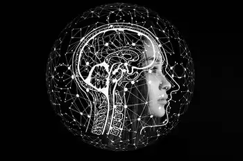
Brain Stimulation is transforming neuromodulation, from TMS and DBS to closed loop devices, targeting neural circuits for addiction, depression, Parkinsons, epilepsy, and chronic pain, powered by advanced imaging, AI analytics, and the NIH BRAIN Initiative.
Key Points
Brain stimulation uses pulses to modulate neural circuits, easing symptoms in depression, Parkinsons, and epilepsy.
✅ Noninvasive TMS and invasive DBS modulate specific brain circuits
✅ Closed loop systems adapt stimulation via real time biomarker detection
✅ Emerging uses: addiction, depression, Parkinsons, epilepsy, chronic pain
In June 2015, biology professor Colleen Hanlon went to a conference on drug dependence. As she met other researchers and wandered around a glitzy Phoenix resort’s conference rooms to learn about the latest work on therapies for drug and alcohol use disorders, she realized that out of the 730 posters, there were only two on brain stimulation as a potential treatment for addiction — both from her own lab at Wake Forest School of Medicine.
Just four years later, she would lead 76 researchers on four continents in writing a consensus article about brain stimulation as an innovative tool for addiction. And in 2020, the Food and Drug Administration approved a transcranial magnetic stimulation device to help patients quit smoking, a milestone for substance use disorders.
Brain stimulation is booming. Hanlon can attend entire conferences devoted to the study of what electrical currents do—including how targeted stimulation can improve short-term memory in older adults—to the intricate networks of highways and backroads that make up the brain’s circuitry. This expanding field of research is slowly revealing truths of the brain: how it works, how it malfunctions, and how electrical impulses, precisely targeted and controlled, might be used to treat psychiatric and neurological disorders.
In the last half-dozen years, researchers have launched investigations into how different forms of neuromodulation affect addiction, depression, loss-of-control eating, tremor, chronic pain, obsessive compulsive disorder, Parkinson’s disease, epilepsy, and more. Early studies have shown subtle electrical jolts to certain brain regions could disrupt circuit abnormalities — the miscommunications — that are thought to underlie many brain diseases, and help ease symptoms that persist despite conventional treatments.
The National Institute of Health’s massive BRAIN Initiative put circuits front and center, distributing $2.4 billion to researchers since 2013 to devise and use new tools to observe interactions between brain cells and circuits. That, in turn, has kindled interest from the private sector. Among the advances that have enhanced our understanding of how distant parts of the brain talk with one another are new imaging technology and the use of machine learning, much as utilities use AI to adapt to shifting electricity demand, to interpret complex brain signals and analyze what happens when circuits go haywire.
Still, the field is in its infancy, and even therapies that have been approved for use in patients with, for example, Parkinson’s disease or epilepsy, help only a minority of patients, and in a world where electricity drives pandemic readiness expectations can outpace evidence. “If it was the Bible, it would be the first chapter of Genesis,” said Michael Okun, executive director of the Norman Fixel Institute for Neurological Diseases at University of Florida Health.
As brain stimulation evolves, researchers face daunting hurdles, and not just scientific ones. How will brain stimulation become accessible to all the patients who need it, given how expensive and invasive some treatments are? Proving to the FDA that brain stimulation works, and does so safely, is complicated and expensive. Even with a swell of scientific momentum and an influx of funding, the agency has so far cleared brain stimulation for only a handful of limited conditions. Persuading insurers to cover the treatments is another challenge altogether. And outside the lab, researchers are debating nascent issues, such as the ethics of mind control, the privacy of a person’s brain data—concerns that echo efforts to develop algorithms to prevent blackouts during rising ransomware threats—and how to best involve patients in the study of the human brain’s far-flung regions.
Neurologist Martha Morrell is optimistic about the future of brain stimulation. She remembers the shocked reactions of her colleagues in 2004 when she left full-time teaching at Stanford (she still has a faculty appointment as a clinical professor of neurology) to direct clinical trials at NeuroPace, then a young company making neurostimulator systems to potentially treat epilepsy patients.
Related: Once a last resort, this pain therapy is getting a new life amid the opioid crisis
“When I started working on this, everybody thought I was insane,” said Morrell. Nearly 20 years in, she sees a parallel between the story of jolting the brain’s circuitry and that of early implantable cardiac devices, such as pacemakers and defibrillators, which initially “were used as a last option, where all other medications have failed.” Now, “the field of cardiology is very comfortable incorporating electrical therapy, device therapy, into routine care. And I think that’s really where we’re going with neurology as well.”
Reaching a ‘slope of enlightenment’
Parkinson’s is, in some ways, an elder in the world of modern brain stimulation, and it shows the potential as well as the limitations of the technology. Surgeons have been implanting electrodes deep in the brains of Parkinson’s patients since the late 1990s, and in people with more advanced disease since the early 2000s.
In that time, it’s gone through the “hype cycle,” said Okun, the national medical adviser to the Parkinson’s Foundation since 2006. Feverish excitement and overinflated expectations have given way to reality, bringing scientists to a “slope of enlightenment,” he said. They have found deep brain stimulation to be very helpful for some patients with Parkinson’s, rendering them almost symptom-free by calming the shaking and tremors that medications couldn’t. But it doesn’t stop the progression of the disease, or resolve some of the problems patients with advanced Parkinson’s have walking, talking, and thinking.
In 2015, the same year Hanlon found only her lab’s research on brain stimulation at the addiction conference, Kevin O’Neill watched one finger on his left hand start doing something “funky.” One finger twitched, then two, then his left arm started tingling and a feeling appeared in his right leg, like it was about to shake but wouldn’t — a tremor.
“I was assuming it was anxiety,” O’Neill, 62, told STAT. He had struggled with anxiety before, and he had endured a stressful year: a separation, selling his home, starting a new job at a law firm in California’s Bay Area. But a year after his symptoms first began, O’Neill was diagnosed with Parkinson’s.
In the broader energy context, California has increasingly turned to battery storage to stabilize its strained grid.
Related: Psychiatric shock therapy, long controversial, may face fresh restrictions
Doctors prescribed him pills that promote the release of dopamine, to offset the death of brain cells that produce this messenger molecule in circuits that control movement. But he took them infrequently because he worried about insomnia as a side effect. Walking became difficult — “I had to kind of think my left leg into moving” — and the labor lawyer found it hard to give presentations and travel to clients’ offices.
A former actor with an outgoing personality, he developed social anxiety and didn’t tell his bosses about his diagnosis for three years, and wouldn’t have, if not for two workdays in summer 2018 when his tremors were severe and obvious.
O’Neill’s tremors are all but gone since he began deep brain stimulation last May, though his left arm shakes when he feels tense.
It was during that period that he learned about deep brain stimulation, at a support group for Parkinson’s patients. “I thought, ‘I will never let anybody fuss with my brain. I’m not going to be a candidate for that,’” he recalled. “It felt like mad scientist science fiction. Like, are you kidding me?”
But over time, the idea became less radical, as O’Neill spoke to DBS patients and doctors and did his own research, and as his symptoms worsened. He decided to go for it. Last May, doctors at the University of California, San Francisco surgically placed three metal leads into his brain, connected by thin cords to two implants in his chest, just near the clavicles. A month later, he went into the lab and researchers turned the device on.
“That was a revelation that day,” he said. “You immediately — literally, immediately — feel the efficacy of these things. … You go from fully symptomatic to non-symptomatic in seconds.”
When his nephew pulled up to the curb to pick him up, O’Neill started dancing, and his nephew teared up. The following day, O’Neill couldn’t wait to get out of bed and go out, even if it was just to pick up his car from the repair shop.
In the year since, O’Neill’s walking has gone from “awkward and painful” to much improved, and his tremors are all but gone. When he is extra frazzled, like while renovating and moving into his new house overlooking the hills of Marin County, he feels tense and his left arm shakes and he worries the DBS is “failing,” but generally he returns to a comfortable, tremor-free baseline.
O’Neill worried about the effects of DBS wearing off but, for now, he can think “in terms of decades, instead of years or months,” he recalled his neurologist telling him. “The fact that I can put away that worry was the big thing.”
He’s just one patient, though. The brain has regions that are mostly uniform across all people. The functions of those regions also tend to be the same. But researchers suspect that how brain regions interact with one another — who mingles with whom, and what conversation they have — and how those mixes and matches cause complex diseases varies from person to person. So brain stimulation looks different for each patient.
Related: New study revives a Mozart sonata as a potential epilepsy therapy
Each case of Parkinson’s manifests slightly differently, and that’s a bit of knowledge that applies to many other diseases, said Okun, who organized the nine-year-old Deep Brain Stimulation Think Tank, where leading researchers convene, review papers, and publish reports on the field’s progress each year.
“I think we’re all collectively coming to the realization that these diseases are not one-size-fits-all,” he said. “We have to really begin to rethink the entire infrastructure, the schema, the framework we start with.”
Brain stimulation is also used frequently to treat people with common forms of epilepsy, and has reduced the number of seizures or improved other symptoms in many patients. Researchers have also been able to collect high-quality data about what happens in the brain during a seizure — including identifying differences between epilepsy types. Still, only about 15% of patients are symptom-free after treatment, according to Robert Gross, a neurosurgery professor at Emory University in Atlanta.
“And that’s a critical difference for people with epilepsy. Because people who are symptom-free can drive,” which means they can get to a job in a place like Georgia, where there is little public transit, he said. So taking neuromodulation “from good to great,” is imperative, Gross said.
Renaissance for an ancient idea
Recent advances are bringing about what Gross sees as “almost a renaissance period” for brain stimulation, though the ideas that undergird the technology are millenia old. Neuromodulation goes back to at least ancient Egypt and Greece, when electrical shocks from a ray, called the “torpedo fish,” were recommended as a treatment for headache and gout. Over centuries, the fish zaps led to doctors burning holes into the brains of patients. Those “lesions” worked, somehow, but nobody could explain why they alleviated some patients’ symptoms, Okun said.
Perhaps the clearest predecessor to today’s technology is electroconvulsive therapy (ECT), which in a rudimentary and dangerous way began being used on patients with depression roughly 100 years ago, said Nolan Williams, director of the Brain Stimulation Lab at Stanford University.
Related: A new index measures the extent and depth of addiction stigma
More modern forms of brain stimulation came about in the United States in the mid-20th century. A common, noninvasive approach is transcranial magnetic stimulation, which involves placing an electromagnetic coil on the scalp to transmit a current into the outermost layer of the brain. Vagus nerve stimulation (VNS), used to treat epilepsy, zaps a nerve that contributes to some seizures.
The most invasive option, deep brain stimulation, involves implanting in the skull a device attached to electrodes embedded in deep brain regions, such as the amygdala, that can’t be reached with other stimulation devices. In 1997, the FDA gave its first green light to deep brain stimulation as a treatment for tremor, and then for Parkinson’s in 2002 and the movement disorder dystonia in 2003.
Even as these treatments were cleared for patients, though, what was happening in the brain remained elusive. But advanced imaging tools now let researchers peer into the brain and map out networks — a recent breakthrough that researchers say has propelled the field of brain stimulation forward as much as increased funding has, paralleling broader efforts to digitize analog electrical systems across industry. Imaging of both human brains and animal models has helped researchers identify the neuroanatomy of diseases, target brain regions with more specificity, and watch what was happening after electrical stimulation.
Another key step has been the shift from open-loop stimulation — a constant stream of electricity — to closed-loop stimulation that delivers targeted, brief jolts in response to a symptom trigger. To make use of the futuristic technology, labs need people to develop artificial intelligence tools, informed by advances in machine learning for the energy transition, to interpret large data sets a brain implant is generating, and to tailor devices based on that information.
“We’ve needed to learn how to be data scientists,” Morrell said.
Affinity groups, like the NIH-funded Open Mind Consortium, have formed to fill that gap. Philip Starr, a neurosurgeon and developer of implantable brain devices at the University of California at San Francisco Health system, leads the effort to teach physicians how to program closed-loop devices, and works to create ethical standards for their use. “There’s been extraordinary innovation after 20 years of no innovation,” he said.
The BRAIN Initiative has been critical, several researchers told STAT. “It’s been a godsend to us,” Gross said. The NIH’s Brain Research through Advancing Innovative Neurotechnologies (BRAIN) Initiative was launched in 2013 during the Obama administration with a $50 million budget. BRAIN now spends over $500 million per year. Since its creation, BRAIN has given over 1,100 awards, according to NIH data. Part of the initiative’s purpose is to pair up researchers with medical technology companies that provide human-grade stimulation devices to the investigators. Nearly three dozen projects have been funded through the investigator-devicemaker partnership program and through one focused on new implantable devices for first-in-human use, according to Nick Langhals, who leads work on neurological disorders at the initiative.
The more BRAIN invests, the more research is spawned. “We learn more about what circuits are involved … which then feeds back into new and more innovative projects,” he said.
Many BRAIN projects are still in early stages, finishing enrollment or small feasibility studies, Langhals said. Over the next couple of years, scientists will begin to see some of the fruits of their labor, which could lead to larger clinical trials, or to companies developing more refined brain stimulation implants, Langhals said.
Money from the National Institutes of Mental Health, as well as the NIH’s Helping to End Addiction Long-term (HEAL), has similarly sweetened the appeal of brain stimulation, both for researchers and industry. “A critical mass” of companies interested in neuromodulation technology has mushroomed where, for two decades, just a handful of companies stood, Starr said.
More and more, pharmaceutical and digital health companies are looking at brain stimulation devices “as possible products for their future,” said Linda Carpenter, director of the Butler Hospital TMS Clinic and Neuromodulation Research Facility.
‘Psychiatry 3.0’
The experience with using brain stimulation to stop tremors and seizures inspired psychiatrists to begin exploring its use as a potentially powerful therapy for healing, or even getting ahead of, mental illness.
In 2008, the FDA approved TMS for patients with major depression who had tried, and not gotten relief from, drug therapy. “That kind of opened the door for all of us,” said Hanlon, a professor and researcher at the Center for Research on Substance Use and Addiction at Wake Forest School of Medicine. The last decade saw a surge of research into how TMS could be used to reset malfunctioning brain circuits involved in anxiety, depression, obsessive-compulsive disorder, and other conditions.
“We’re certainly entering into what a lot of people are calling psychiatry 3.0,” Stanford’s Williams said. “Whereas the first iteration was Freud and all that business, the second one was the psychopharmacology boom, and this third one is this bit around circuits and stimulation.”
Drugs alleviate some patients’ symptoms while simultaneously failing to help many others, but psychopharmacology clearly showed “there’s definitely a biology to this problem,” Williams said — a biology that in some cases may be more amenable to a brain stimulation.
Related: Largest psilocybin trial finds the psychedelic is effective in treating serious depression
The exact mechanics of what happens between cells when brain circuits … well, short-circuit, is unclear. Researchers are getting closer to finding biomarkers that warn of an incoming depressive episode, or wave of anxiety, or loss of impulse control. Those brain signatures could be different for every patient. If researchers can find molecular biomarkers for psychiatric disorders — and find ways to preempt those symptoms by shocking particular brain regions — that would reshape the field, Williams said.
Not only would disease-specific markers help clinicians diagnose people, but they could help chip away at the stigma that paints mental illness as a personal or moral failing instead of a disease. That’s what happened for epilepsy in the 1960s, when scientific findings nudged the general public toward a deeper understanding of why seizures happen, and it’s “the same trajectory” Williams said he sees for depression.
His research at the Stanford lab also includes work on suicide, and obsessive-compulsive disorder, which the FDA said in 2018 could be treated using noninvasive TMS. Williams considers brain stimulation, with its instantaneity, to be a potential breakthrough for urgent psychiatric situations. Doctors know what to do when a patient is rushed into the emergency room with a heart attack or a stroke, but there is no immediate treatment for psychiatric emergencies, he said. Williams wonders: What if, in the future, a suicidal patient could receive TMS in the emergency room and be quickly pulled out of their depressive mental spiral?
Researchers are also actively investigating the brain biology of addiction. In August 2020, the FDA approved TMS for smoking cessation, the first such OK for a substance use disorder, which is “really exciting,” Hanlon said. Although there is some nuance when comparing substance use disorders, a primal mechanism generally defines addiction: the eternal competition between “top-down” executive control functions and “bottom-up” cravings. It’s the same process that is at work when one is deciding whether to eat another cookie or abstain — just exacerbated.
Hanlon is trying to figure out if the stop and go circuits are in the same place for all people, and whether neuromodulation should be used to strengthen top-down control or weaken bottom-up cravings. Just as brain stimulation can be used to disrupt cellular misfiring, it could also be a tool for reinforcing helpful brain functions, or for giving the addicted brain what it wants in order to curb substance use.
Evidence suggests many people with schizophrenia smoke cigarettes (a leading cause of early death for this population) because nicotine reduces the “hyperconnectivity” that characterizes the brains of people with the disease, said Heather Ward, a research fellow at Boston’s Beth Israel Deaconess Medical Center. She suspects TMS could mimic that effect, and therefore reduce cravings and some symptoms of the disease, and she hopes to prove that in a pilot study that is now enrolling patients.
If the scientific evidence proves out, clinicians say brain stimulation could be used alongside behavioral therapy and drug-based therapy to treat substance use disorders. “In the end, we’re going to need all three to help people stay sober,” Hanlon said. “We’re adding another tool to the physician’s toolbox.”
Decoding the mysteries of pain
Afavorable outcome to the ongoing research, one that would fling the doors to brain stimulation wide open for patients with myriad disorders, is far from guaranteed. Chronic pain researchers know that firsthand.
Chronic pain, among the most mysterious and hard-to-study medical phenomena, was the first use for which the FDA approved deep brain stimulation, said Prasad Shirvalkar, an assistant professor of anesthesiology at UCSF. But when studies didn’t pan out after a year, the FDA retracted its approval.
Shirvalkar is working with Starr and neurosurgeon Edward Chang on a profoundly complex problem: “decoding pain in the brain states, which has never been done,” as Starr told STAT.
Part of the difficulty of studying pain is that there is no objective way to measure it. Much of what we know about pain is from rudimentary surveys that ask patients to rate how much they’re hurting, on a scale from zero to 10.
Using implantable brain stimulation devices, the researchers ask patients for a 0-to-10 rating of their pain while recording up-and-down cycles of activity in the brain. They then use machine learning to compare the two streams of information and see what brain activity correlates with a patient’s subjective pain experience. Implantable devices let researchers collect data over weeks and months, instead of basing findings on small snippets of information, allowing for a much richer analysis.
Related News