3 Phase Transformers
By R.W. Hurst, Editor
By R.W. Hurst, Editor
Our customized live online or in‑person group training can be delivered to your staff at your location.

3 phase transformers step voltage up or down using delta or wye connections. Built with laminated cores and robust insulation, they balance loads, improve efficiency, and serve industrial, utility, and pad-mounted distribution applications.
Although three single-phase transformers can be connected to form a bank, purpose-built three-phase units are more efficient. They require less material, are more compact, and are lighter for the same kVA rating. For these reasons, they are the standard choice for large-scale applications. This makes them a preferred choice for large-scale applications. For a broader understanding of how these units fit into the grid, see our overview of power transformers.
Electrical Transformer Maintenance Training
Substation Maintenance Training
Request a Free Training Quotation
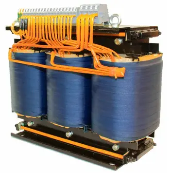
A typical 3 phase transformer is built by winding three single-phase windings onto a shared laminated steel core. The unit is enclosed and often filled with dielectric oil, which insulates the windings, provides cooling, and prevents moisture damage. Dry-type transformers, by contrast, utilize air or resin insulation and are typically chosen for indoor settings where fire safety is a critical concern.
Core designs vary:
Laminated cores minimize eddy current losses.
Toroidal cores reduce magnetic leakage, lower noise, and improve efficiency.
The winding design and insulation determine load handling and voltage regulation. In step-down units, the primary windings are connected to a higher supply voltage, while the secondary windings deliver a reduced voltage for distribution or equipment. For a deeper background, see Construction of a Transformer. For a look at how electrical energy is transferred between circuits, read our explainer on how transformers work.
The way windings are arranged — Delta (Δ) or Wye/Star (Y) — defines how a transformer behaves in a system:
Download our FREE Electrical Training Catalog and explore a full range of expert-led electrical training courses.

Delta–Delta (Δ/Δ): No phase shift, handles unbalanced loads, continues operation if one winding fails.
Delta–Wye (Δ/Y): Common for stepping down voltage, provides both three-phase and single-phase outputs.
Wye–Delta (Y/Δ): Often used to step up generator voltages for transmission.
Wye–Wye (Y/Y): Provides grounding on both sides, useful for harmonics control.
Specialized designs include:
Open Delta: Supplies three-phase loads with only two transformers (reduced capacity).
Zigzag grounding transformers: Create a neutral point and manage zero-sequence currents for stability.
These connections determine phase shift, vector group classification, and compatibility when paralleling transformers.
Some designs utilize open-delta configurations to supply three-phase loads with only two transformers, or employ zigzag grounding transformers to create a neutral and manage zero-sequence currents, thereby improving system stability under unbalanced load conditions. In distribution systems, a 3 phase pad-mounted transformer provides safe, ground-level voltage conversion for residential and commercial customers.
Every three-phase transformer has a vector group designation (e.g., Yd11, Dy1). This indicates the winding connections and the phase angle difference between primary and secondary voltages. Correct vector group selection is critical when transformers operate in parallel, ensuring phase alignment and preventing circulating currents.
| Feature | Three Phase Transformers | Single-Phase Transformers |
|---|---|---|
| Efficiency | Higher efficiency due to continuous balanced power delivery | Lower efficiency, especially for high-capacity applications |
| Material Usage | Requires less conductor material for the same power output | Requires more material for equivalent output |
| Size and Weight | More compact and lighter for the same kVA rating | Larger and heavier for equivalent capacity |
| Load Handling | Handles heavy industrial loads with better voltage regulation | Best suited for smaller, lighter loads |
| Installation | Requires specialized equipment for transport and installation as one unit | Easier to transport and install individually |
| Redundancy | Failure of one coil may require removal of the entire unit | If one unit fails, others can still operate in a bank |
| Cost | Lower cost per kVA in large-scale applications | Higher cost per kVA for the same output |
With voltages spaced 120 degrees apart, three-phase power delivers continuous energy with less conductor material. This efficiency makes it the global standard for long-distance transmission, industrial equipment, and large commercial facilities. Three-phase transformers adapt these systems to match generation output, transmission requirements, and load needs.
Compared to single-phase transformer banks, three-phase units offer higher efficiency, lower cost per kVA, lighter weight, and reduced space requirements. However, single-phase units can be easier to transport, install, and replace if one fails, whereas repairing an integrated three-phase transformer may require removing the entire unit.
Advantages:
Higher efficiency than single-phase banks
Lower cost per kVA
Smaller size and lighter weight
Better load balancing and reduced losses
Disadvantages:
More challenging to transport and install as one unit
A single coil failure can require removing the entire transformer
3 phase transformers are found in substation installations, pad-mounted units for underground distribution, and renewable energy systems connecting wind or solar farms to the grid. They are also used in industrial plants, large commercial facilities, and regional utility networks to ensure consistent, efficient power delivery.
Three-phase transformers are critical components in today’s electrical networks. They offer high efficiency, compact construction, and flexibility in voltage transformation. With various winding configurations, robust insulation systems, and precise vector group classifications, they deliver reliable and efficient power for industrial, commercial, and utility-scale applications. Distribution networks often rely on electrical substation transformers to step voltages up or down for efficient transmission.
3 phase transformers are used across the utility and industrial sectors:
Substations: Stepping voltage up or down for transmission and distribution
Pad-mounted units: Providing safe, ground-level service in urban or suburban areas (Pad-Mounted Transformers)
Renewable energy systems: Connecting wind farms and solar plants to the grid
Industrial facilities: Supplying motors, drives, and heavy loads
Regional networks: Enabling long-distance bulk power transfer
![]()
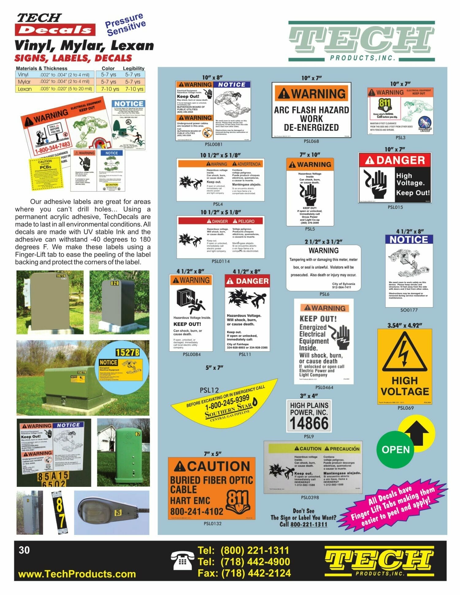
A special application is the 3 phase pad-mounted transformer, which steps down medium voltage (2.4–35 kV) to lower levels suitable for end-use. Installed outdoors on concrete pads, these enclosed units are common in underground distribution systems.
Advantages include:
Compact, visually unobtrusive design
Enhanced safety with dead-front construction
Use of biodegradable insulating fluids for environmental safety
High reliability for critical loads like data centers
Simplified installation and maintenance
Stay informed with our FREE Utility Transformers Newsletter — get the latest news, breakthrough technologies, and expert insights, delivered straight to your inbox.
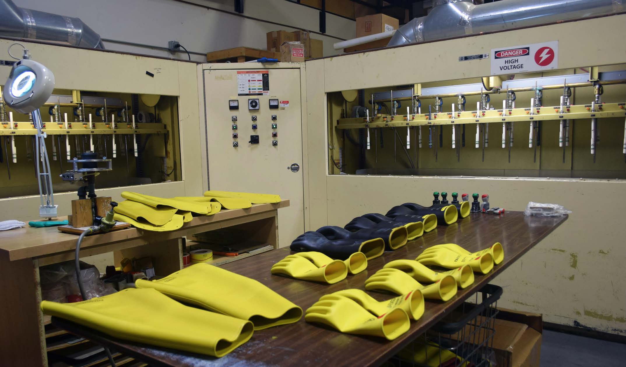
Routine inspections are crucial for preventing overheating, insulation breakdown, and mechanical wear. Oil-filled units require periodic oil analysis to assess dielectric quality and detect moisture ingress. Thermal imaging is often used to locate hot spots in windings and cores, allowing early repairs and extending service life. When grounding is required for system stability, grounding transformers are used to create a neutral and manage unbalanced loads.
Delta (Δ) windings form a closed triangle, providing higher line-to-line voltage and excellent load balancing for heavy loads. Star (Wye, Y) windings connect to a neutral point, resulting in lower phase voltages and allowing for grounded neutrals, which enhances safety.
They deliver continuous, balanced power with reduced fluctuation, utilizing a single integrated core instead of three separate units, which in turn reduces losses, costs, and size.
They power industrial motors, commercial buildings, substations, renewable energy connections, and utility grids.
Core-type is cost-effective for lower ratings. Shell-type offers greater strength and efficiency at high currents or voltages. Space, cooling, and load demand determine the choice.
The turns ratio sets the voltage output. Balanced, well-designed windings enhance regulation, prevent overheating, and ensure stability under varying load conditions.
It identifies winding connections and phase shift. Matching vector groups ensures compatibility and prevents circulating currents in parallel systems.
Dry-type uses air cooling, is safer indoors, and has lower maintenance. Oil-filled units utilize insulating oil for enhanced efficiency and capacity, but they require specific safety precautions.
Three-phase transformers are critical for the global power system. With diverse winding connections, robust insulation systems, and efficient core designs, they provide reliable voltage transformation for every part of the grid. From substations and renewable energy systems to pad-mounted transformers, these units ensure that electricity is delivered safely and efficiently to industries, businesses, and communities.
Advantages To Instructor-Led Training – Instructor-Led Course, Customized Training, Multiple Locations, Economical, CEU Credits, Course Discounts.
Request For QuotationWhether you would prefer Live Online or In-Person instruction, our electrical training courses can be tailored to meet your company's specific requirements and delivered to your employees in one location or at various locations.