DC Generator Explained
By William Conklin, Associate Editor
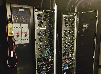
UPS System Training
Our customized live online or in‑person group training can be delivered to your staff at your location.
- Live Online
- 12 hours Instructor-led
- Group Training Available
Download Our NFPA 70E Fact Sheet – 2024 Electrical Safety Edition
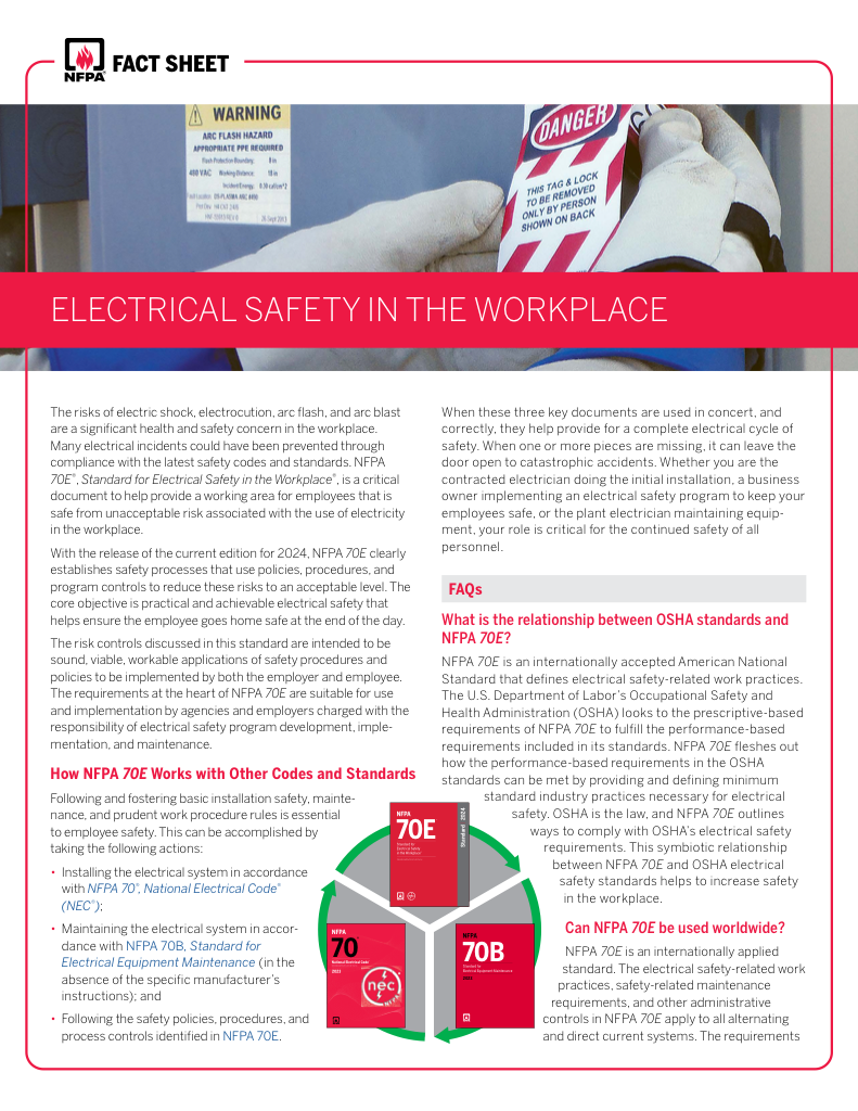
- Understand how NFPA 70E works with NEC and NFPA 70B standards
- Clarify the shared responsibility between employers and employees
- Learn how NFPA 70E supports OSHA compliance
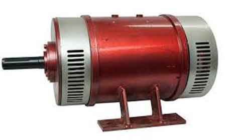
A DC generator converts mechanical energy into direct current electricity for use in backup power systems, industrial machines, and battery charging. It provides reliable, consistent DC power output for various electrical and energy conversion applications.
What is a DC Generator?
A DC generator is an electromechanical device that produces direct current by converting mechanical energy.
✅ Converts mechanical energy into direct current electricity
✅ Used in battery charging, backup power, and industrial systems
✅ Delivers consistent voltage for energy conversion and power supply
Emergency Generator Standby Power Training
Power Quality Analysis Training
Request a Free Emergency Generator Training Quotation
A DC generator is vital in converting mechanical energy into electrical energy. By employing the principles of electromagnetic induction, this versatile machine has powered various applications across industries. However, as technology advances, understanding its fundamental workings, types, and maintenance remains crucial for professionals and enthusiasts alike. Our article on emergency power supply explains how these systems provide seamless transitions during utility failures.
In today's world of rapidly evolving technology, one often comes across devices that can convert mechanical energy into electricity. One such device is the DC generator, which has existed for over a century. As a fundamental part of the electrical industry, DC generators have powered countless applications, including small-scale electronics, vehicles, and large industrial machines. Our guide on emergency backup generators explains how these systems keep critical loads running during outages.
Electromagnetic Induction: The Principle Behind DC Power Generation
To understand the workings of a DC generator, we must first explore the concept of electromagnetic induction. This phenomenon, discovered by Michael Faraday in the early 19th century, states that a voltage, or electromotive force (EMF), can be induced in a conductor when it is exposed to a changing magnetic field. This induced EMF drives the flow of electric current, producing electricity. DC generators rely on this principle to generate Direct Current. For a broader overview of how engines operate, explore our article on how a generator works.
Sign Up for Electricity Forum’s Generators/UPS Newsletter
Stay informed with our FREE Generators/UPS Newsletter — get the latest news, breakthrough technologies, and expert insights, delivered straight to your inbox.
Key Components
The primary components are the stator, rotor, armature, field winding, commutator, and brushes. The stator houses the stationary magnetic field, which can be generated by permanent magnets or field coils. The rotor, on the other hand, contains the armature windings where the EMF is induced. As the rotor rotates within the magnetic field, voltage is generated in the armature windings through electromagnetic induction.
How a Commutator Converts AC to DC
The commutator, a crucial component, is responsible for converting the alternating current (AC) produced in the armature windings into Direct Current. It continuously changes the connections between the armature windings and the external circuit, ensuring the current flows in one direction. In addition, brushes maintain contact with the commutator, transferring the generated electricity to the external circuit.
DC Generator vs. AC Generator: What’s the Difference?
A DC generator produces a direct current, which flows in a single, constant direction. In a DC generator, a commutator ensures that the current generated in the armature windings always flows in the same direction. This is achieved by continuously changing the connections between the armature windings and the external circuit. As a result, the output voltage and current remain constant in polarity. They are used in applications requiring a stable voltage supply, such as charging batteries, powering small electronic devices, or operating DC motors.
An AC generator, an alternator, produces an alternating current that periodically reverses direction. AC generators do not require a commutator, as the output current can change direction naturally due to the rotation of the armature within the magnetic field. The output voltage and current follow a sinusoidal waveform, meaning they vary in magnitude and direction over time. AC generators are more commonly used than DC generators, as AC power can be easily transformed to different voltage levels and is more efficient for long-distance transmission. Most power grids and household electricity supplies rely on AC power.
The main difference between it and an AC generator is the type of electrical current they generate. They produce a constant unidirectional current, while AC generators produce a sinusoidal current that reverses direction periodically. Both types have their specific applications and advantages, depending on the requirements of the electrical system they are used in. Learn how different battery backup systems work to keep critical loads powered during outages.
Types and Their Applications
Several types of DC generators exist, including series-wound, shunt-wound, and compound-wound devices. These classifications are based on how the field winding is connected to the armature winding. Each type has its unique characteristics, making it suitable for specific applications.
Series-wound units have the armature and field windings connected in series. They provide high current but relatively low voltage output, making them suitable for starting large motors or powering arc welding machines. In contrast, shunt-wound types have their field windings connected in parallel with the armature, providing a more stable output voltage suitable for battery charging and lighting systems. Finally, compound-wound types have both series and shunt windings, offering the advantages of both types and finding use in applications requiring stable output voltage with varying loads. Discover how an automatic transfer switch ensures seamless transitions between utility and electrical power.
Voltage Regulation and Efficiency
The output voltage can be regulated through various means, such as adjusting the field current, employing voltage regulators, or using feedback systems. These methods ensure the generated voltage remains stable, even under varying load conditions, safeguarding the connected devices from damage due to voltage fluctuations. Interested in long-term performance? Learn how long battery backups last and what factors affect their reliability.
Test Your Knowledge About Generators/UPS!
Think you know Generators/UPS? Take our quick, interactive quiz and test your knowledge in minutes.
- Instantly see your results and score
- Identify strengths and areas for improvement
- Challenge yourself on real-world electrical topics
DC Generator Maintenance and Troubleshooting Tips
Proper maintenance and troubleshooting are essential for its long-lasting operation. Regular inspection of brushes, bearings, and other components, as well as lubrication and cleaning, is necessary to prevent premature wear and tear. Additionally, any performance irregularities should be promptly addressed by assessing the output voltage, load resistance, and other factors to identify and rectify the underlying issues. For a deeper look into reliable backup power solutions, check out our section on emergency backup generators.
Related Articles


