Power System Protection
By Bill Brown, P.E., Square D Engineering Services
Protective Relay Training - Basic
Our customized live online or in‑person group training can be delivered to your staff at your location.
- Live Online
- 12 hours Instructor-led
- Group Training Available
Download Our NFPA 70E Fact Sheet – 2024 Electrical Safety Edition
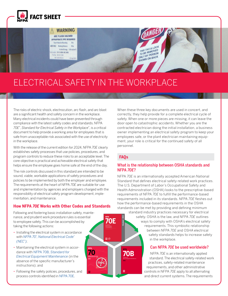
- Understand how NFPA 70E works with NEC and NFPA 70B standards
- Clarify the shared responsibility between employers and employees
- Learn how NFPA 70E supports OSHA compliance
Power system protection ensures the reliable operation of electrical grids by detecting faults, isolating failures, and safeguarding equipment and personnel. It maintains stability, improves safety, and supports compliance with industry standards.
What is Power System Protection?
Power system protection is a coordinated set of devices and methods designed to detect, isolate, and minimize the impact of electrical faults in electrical networks.
✅ Detects and clears faults to maintain grid stability
✅ Protects transformers, lines, and switchgear from damage
✅ Enhances safety, reliability, and compliance with standards
Power System Protection Courses
Short Circuit Study & Protective Device Coordination
Arc Flash Analysis/Study - IEEE 1584 Update
An important consideration in electrical system design is power system protection. Without system protection, the power system itself, which is intended to be of benefit to the facility in question, would itself become a hazard. Training in basic protective relay equips professionals with the knowledge to design, test, and maintain critical protection systems.
The major concern for power system protection is protection against the effects of destructive, abnormally high currents. These abnormal currents, if left unchecked, could cause fires or explosions, posing a risk to personnel and damaging equipment. Other concerns, such as transient overvoltages, are also considered when designing power system protection, although they are typically addressed only after protection against abnormal currents has been established. Understanding overcurrent protection is essential, since abnormal fault currents can cause fires, explosions, and equipment damage if not properly managed.
Characterization of power system protection faults
Any current in excess of the rated current of equipment or the ampacity of a conductor may be considered an overcurrent. Overcurrents can generally be categorized as overloads or faults. An overload is a condition where load equipment draws more current than the system can safely supply. The main hazard with overload conditions is the thermal heating effects of overloaded equipment and conductors. Faults are unintentional connections in the electrical system that result in overcurrents of a magnitude much larger than overloads. Protective relay technology forms the backbone of fault detection, ensuring fast and accurate isolation of dangerous conditions within the grid.
FREE EF Electrical Training Catalog
Download our FREE Electrical Training Catalog and explore a full range of expert-led electrical training courses.

- Live online and in-person courses available
- Real-time instruction with Q&A from industry experts
- Flexible scheduling for your convenience
Electrical Faults
Faults can be categorized in several different ways. A fault with very little impedance in the unintended connection is referred to as a short circuit or bolted fault (the latter term is used due to the fact that a short circuit can be thought of as a bus bar inadvertently bolted across two phase conductors or from phase to ground). A fault to ground is referred to as a ground fault. A fault between all three phases is referred to as a 3-phase fault. A fault between two phases is referred to as a phase-to-phase fault. A fault that contains enough impedance in the unintentional connection to significantly affect the fault current compared to a true short circuit is known as an impedance fault. An arcing fault occurs when an unintentional connection is made via an electrical arc through an ionized gas, such as air. All of these terms are used in practice to characterize the nature of a fault.
In order to quantitatively characterize a fault, it is necessary to calculate how much fault current could be produced at a given location in the system. In most cases, this will be the three-phase short-circuit current, which is the current produced if all three phases were shorted to each other and/or to ground. The simplest method for illustrating this is to reduce the power system at the point in question to its Thevenin equivalent. The Thevenin equivalent is the equivalent single voltage source and impedance that produces the same short-circuit results as the electrical system itself. The Thevenin equivalent voltage Vth is the open-circuit voltage at the point in question, and the Thevenin equivalent impedance Zth is the impedance of the electrical system at the point in question with the source voltage equal to zero. If a further simplification is made such that the system can be reduced to its single-phase equivalent, then a simple 3-phase fault current calculation for the three-phase fault current If3ø can be performed as shown in Figure 1:
Fig. 1 - Simplified 3-phase fault calculation
The Thevenin impedance for a electrical system at a given point is referred to as the short-circuit impedance. In the vast majority of power systems, the short-circuit impedance is predominantly inductive; therefore, a simplification often made is to treat the impedance purely as inductance. This has the effect of causing the fault current to lag the system line-to-neutral voltage by 90°. If the system is an ungrounded delta system, the equivalent line-to-neutral voltage can be obtained by performing a delta-wye conversion of the source voltage. Engineers often apply relay and circuit breaker coordination to ensure that faults are cleared in the correct sequence, thereby minimizing disruptions to the electrical system.
The phase-to-phase fault value can be calculated from the three-phase fault value if it is remembered that the line-to-line voltage magnitude is equal to the line-to-neutral voltage magnitude multiplied by √3, and that there will be twice the impedance in the circuit since the return path must be considered. These two facts, taken together, allow computation of the line-to-line fault current magnitude. Advanced short circuit protection strategies help utilities and industries maintain safe operating conditions even during severe fault events.
A key part of system defense is transformer protection, which safeguards critical assets against overloads, faults, and insulation failures.
Related Articles


