Power Transformers
Substation Maintenance Training
Our customized live online or in‑person group training can be delivered to your staff at your location.
- Live Online
- 12 hours Instructor-led
- Group Training Available
Download Our OSHA 3075 Fact Sheet – Understanding Electrical Hazards in the Workplace
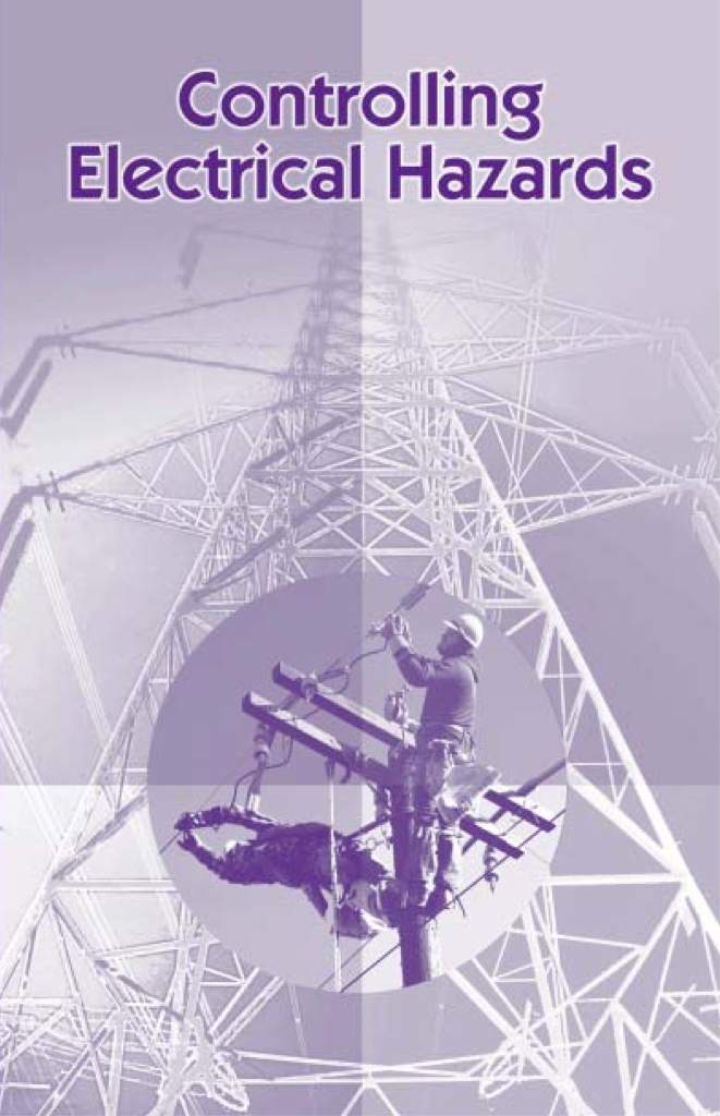
- Learn the effects of electric current on the human body
- Understand OSHA safety standards and protective devices
- Discover essential lockout/tagout and grounding practices
Power transformers step up or down the voltage in transmission networks. Built with laminated cores, copper windings, and insulation, they ensure efficiency, regulate current, and deliver stable electricity for utility, industrial, and substation applications.
What are Power Transformers?
Power transformers are high-voltage electrical devices that transfer energy between circuits using electromagnetic induction, ensuring efficient transmission and distribution.
✅ Convert voltage for long-distance transmission and local distribution
✅ Use laminated cores, copper windings, and dielectric insulation for efficiency
✅ Essential in substations, industrial plants, and utility power grids
Electrical Transformer Maintenance Training
Substation Maintenance Training
Request a Free Training Quotation
Power Transformers – Definition, Construction, and Role in the Grid
Power transformers are the heavy lifters of the grid. They step the voltage up for efficient long-distance transmission and step it down so power can be delivered safely to regional networks. Built around laminated steel cores, copper or aluminum windings, and robust insulation systems, these high-voltage machines minimize losses, stabilize voltage, and ensure the continued operation of industrial, commercial, and utility systems. For background on the science behind energy transfer, see our guide on how do transformers work.
A power transformer transfers energy between circuits through electromagnetic induction, using a magnetic core and tightly engineered windings to change voltage without altering frequency. Unlike distribution units (optimized for continuous partial load), power transformers typically operate near full load and at very high voltages for bulk power flow. In generating stations, they step up generator output to transmission levels; at the grid edge, they step down for regional networks and hand off to distribution equipment inside an Electrical Substation Transformer. In short, power transformers do the heavy lifting, allowing distribution transformers to safely complete the job.
Role in the Electrical Grid
Every stage of the power system depends on transformers designed for specific functions.
-
Generation → Transmission: Step-Up Transformers raise voltage (and lower current) so power can travel hundreds of kilometres with reduced line losses.
-
Transmission Backbone: High Voltage Transformers at 230 kV, 400 kV, and beyond move bulk energy between regions.
-
Regional Handoffs: Substation Transformers adapt voltage for local grids and industrial corridors.
-
Final Delivery: Distribution Transformers reduce voltage to service levels, using formats that match the environment—PadMount Transformer for urban vaults and campuses, Pole Mounted Transformers for overhead rural lines, and Underground for dense city cores.
Test Your Knowledge About Utility Transformers!
Think you know Utility Transformers? Take our quick, interactive quiz and test your knowledge in minutes.
- Instantly see your results and score
- Identify strengths and areas for improvement
- Challenge yourself on real-world electrical topics
Types of Power Transformers
Different designs solve different problems—what changes is the voltage, location, and duty:
-
Step-Up / Step-Down: The classic grid pair. Step up at the plant, step down near load centers. (See Step-Up Transformers.)
-
Three-Phase Units: The utility standard for efficiency and footprint, with connection options covered in 3 Phase Transformers.
-
Autotransformers: Shared-winding designs that save copper and losses when only modest voltage change is required—see What Is an Autotransformer.
-
Medium-Voltage / High-Voltage: Secondary substations and industrial feeders lean on Medium Voltage Transformers, while long-haul corridors depend on High Voltage Transformers.
-
Line-Mounted: For specific corridors or taps, utilities use Powerline Transformers.
All of these sit within your broader Utility Transformers ecosystem.
Design and Construction
The performance and reliability of a power transformer depend on precise design.
-
Core – Built from laminated silicon steel to guide magnetic flux and reduce losses. See our page on the transformer core.
-
Windings – Copper or aluminum coils wrapped around the core; winding design determines voltage ratios. Learn more about transformer windings.
-
Insulation – Oil, resin, or specialized paper prevents electrical shorts and overheating. Details at transformer insulation.
-
Cooling Systems – Transformer oil provides both cooling and dielectric strength; large units use pumps and radiators.
-
Components – Bushings, tap changers, and other transformer components adapt units to load conditions and protect against surges.
To explore assembly methods, refer to our guide on the construction of a transformer.
Efficiency and Energy Losses
Transformers are designed to minimize wasted energy, but two types of losses remain:
-
No-load losses – Core losses caused by hysteresis and eddy currents when energized.
-
Load losses – Resistance in windings, eddy currents, and stray flux during operation.
Because power transformers typically operate near their design point, they achieve very high efficiencies, whereas distribution units—optimized for 24/7 availability—reach peak efficiency at partial load. Oil management and cooling design are central—see Transformer Oil—as are proper Transformer Overcurrent Protection strategies.
Testing, Monitoring, and Reliability
Before service, transformers undergo rigorous validation, including dielectric (high-potential/impulse/induced), polarity, and ratio checks, temperature rise, and load/no-load measurements. In operation, continuous condition awareness is the goal. Hydrogen Detection Systems and Hydrogen Leak Detectors flag incipient faults. Maintenance Inspection Windows enable targeted inspections. Broader analytics are covered in Condition Monitoring in an Age of Modernization. Many operators consolidate this into a Power Transformers Health Check to prioritize interventions.
Applications in Electricity Distribution
Power transformers appear in nearly every part of the grid:
-
Generating plants use step-up units to prepare electricity for transmission.
-
Transmission lines depend on high-voltage transformers to minimize losses.
-
Regional substations adjust voltages for communities and industries.
-
Industrial facilities use transformers to power motors, drives, and heavy equipment.
-
Renewable energy systems rely on transformers to connect wind and solar farms.
Supporting technologies, such as voltage transformers and grounding transformers, enhance stability, measurement, and safety in these networks.
Sizing, Protection, and Connections (Quick Guidance)
Specifying a unit involves aligning kV/kVA, impedance, and connections with the grid's needs. Connection choice (delta/wye, vector groups) affects harmonics, grounding, and paralleling. Early scoping often references Typical Transformer Sizes and application-level topics, such as what causes voltage to Be Induced in a Transformer or what is the Function of a Transformer. For AC fundamentals, see AC Transformer; for practical integration work, Wiring a Transformer helps ground the details. Supplier research can start with Transformer Manufacturers.
Maintenance and Reliability
Regular maintenance ensures transformers operate safely and efficiently for decades.
-
Oil testing checks dielectric strength and moisture content.
-
Thermal imaging identifies hot spots in cores and windings.
-
Winding resistance checks detect imbalances or degradation.
-
Visual inspections catch leaks or insulation breakdowns.
Many utilities employ structured programs like a power transformers health check to avoid unexpected failures.
History of Power Transformers
The principle of induction was discovered in the 1830s, laying the foundation for transformers. By the 1880s, practical transformer designs emerged, and by the 1950s, units rated at 400 kV were in service. By the 1970s, single-unit ratings reached 1100 MVA, with 800 kV and higher units appearing in the 1980s. Today, power transformers continue to evolve, integrating digital monitoring and smart grid technologies.
Sign Up for Electricity Forum’s Utility Transformers Newsletter
Stay informed with our FREE Utility Transformers Newsletter — get the latest news, breakthrough technologies, and expert insights, delivered straight to your inbox.
Frequently Asked Questions
What is a power transformer and how does it work?
It is a device that transfers electricity between circuits using electromagnetic induction, stepping voltage up or down for efficient transmission and safe distribution.
How are power transformers different from distribution transformers?
Power transformers handle high voltages and operate near full load, while distribution transformers manage lower voltages and run 24/7 at partial loads.
What are the main components of a power transformer?
Core, windings, insulation, tap changer, bushings — each ensures efficient and safe voltage conversion.
Why is regular maintenance important?
Insulation, windings, and oil degrade over time. Preventive testing and inspections avoid costly failures and keep systems reliable.
Power transformers are the backbone of the electricity delivery system. From stepping up generator output to managing high-voltage transmission and stepping it down again for local use, they enable safe and efficient energy transfer across continents. With strong construction, modern monitoring, and regular maintenance, they remain indispensable to both traditional utilities and the smart grids of the future.
Related Articles


