Grounding and Bonding NEC Installations
By Frank Baker, Technical Editor
By Frank Baker, Technical Editor
Our customized live online or in‑person group training can be delivered to your staff at your location.

Grounding and bonding NEC installations rely on coordinated fault-current paths and stable system references. This guide explains how NEC intent translates into predictable behavior at service equipment, raceways, and enclosures without restating grounding fundamentals already covered in the primary grounding resources.
This article focuses on how NEC grounding and bonding function together in real installations, clarifying intent, coordination, and inspection realities rather than teaching grounding theory or summarizing Article 250 line by line.
Grounding and bonding under the NEC depend less on memorized rules than on understanding how fault current is expected to move through a system. The National Electrical Code does not treat grounding and bonding as parallel checklists. It treats them as a coordinated safety architecture that determines whether protective devices operate correctly and whether exposed metal remains safe to touch.
In practice, many NEC grounding issues arise not from missing conductors but from misunderstanding how those conductors are intended to function together. Installations can appear compliant while behaving unpredictably during abnormal conditions.
This page explains how grounding and bonding decisions under NEC intent influence system behavior at service equipment, raceways, enclosures, and derived systems. Canadian and U.S. bonding rules only make sense when interpreted within the broader framework of electrical grounding.
NEC Article 250 is often approached as a collection of rules. In the field, it behaves more like a performance system.
The NEC expects:
• A predictable fault-current return path
• Limited touch voltage during abnormal conditions
• Continuous bonding between conductive parts
• A stable system reference
When these outcomes are achieved, compliance follows naturally. When they are not, installations may pass inspection yet still exhibit unsafe or inconsistent behavior during faults.
Think you know Power Quality? Take our quick, interactive quiz and test your knowledge in minutes.
Grounding and bonding NEC installations succeed when Article 250 is read as a system description rather than a checklist of isolated requirements.
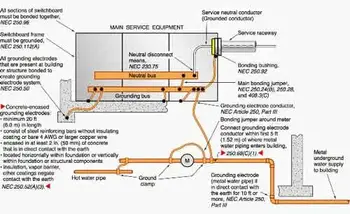
The NEC does not ground equipment for convenience. It grounds equipment so fault current has a deliberate, low-impedance path back to its source.
Bonding establishes that path.
Grounding stabilizes the reference.
When either is compromised, fault current disperses. Breakers hesitate. Metal parts rise in voltage. The system appears intact while operating in a degraded safety state. This behavior is often first observed at grounding electrodes, which form the physical foundation of the fault-current return path in NEC systems, as explained in grounding electrodes.
NEC grounding and bonding are therefore not primarily about earth. They are about circuit completion and fault clearing.
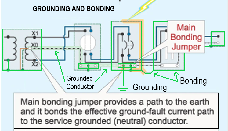
Bonding is the silent workhorse of NEC grounding systems.
Every enclosure, raceway, connector, and bonding jumper either strengthens or weakens the fault-clearing circuit. Loose fittings, painted joints, or assumed continuity are common points where NEC intent breaks down in practice.
Bonding under NEC installations succeeds when it is:
• Mechanically reliable
• Electrically continuous
• Intentionally routed
It fails when continuity is assumed rather than verified. In medium-voltage and industrial systems, bonding effectiveness is closely tied to neutral grounding methods, particularly when neutral grounding resistors are used to control fault current magnitude and behavior.
Grounding under the NEC establishes the system reference point around which bonding equalizes potential.
Without that reference, voltage has no anchor.
Without bonding, the reference has no reach.
The NEC treats grounding and bonding as complementary functions because neither can perform its role in isolation. This relationship becomes especially clear when grounding is applied to rotating machines such as generators, as outlined in grounding a generator.
Separately derived systems quickly expose grounding and bonding errors.
Transformer secondaries, generators, and alternate power sources all require deliberate grounding and bonding decisions. When those decisions are copied mechanically from unrelated installations, circulating currents, nuisance tripping, and unstable voltages often follow, particularly in systems that depend on proper transformer grounding design.
NEC grounding and bonding must always be interpreted within the context of the specific system configuration rather than transferred blindly from one installation to another.
Inspectors rarely evaluate NEC grounding and bonding based on theoretical explanations. They assess continuity, termination quality, conductor routing, and physical integrity.
A well-coordinated NEC grounding system looks simple.
A poorly coordinated one looks complicated.
The difference is not in the code language itself. It is in how that language was understood and applied. This contrast becomes especially visible in large facilities where substation grounding must integrate multiple grounding paths into a single reference system.
While fault clearing remains the primary NEC objective, grounding and bonding also influence:
• Surge protective device performance
• EMI susceptibility
• Control system stability
• Long-term connector reliability
These outcomes are not controlled by grounding or bonding alone. They emerge from how the two functions are coordinated, particularly in safety-critical environments where electrical safety grounding governs both shock protection and arc-flash risk.
Grounding provides the reference.
Bonding completes the circuit.
Coordination makes the system predictable.
That predictability allows NEC installations to remain safe long after drawings are forgotten and equipment is modified.
The NEC does not ask whether grounding and bonding are merely present. It asks whether they function together as a coordinated system.
Stay informed with our FREE Power Quality Newsletter — get the latest news, breakthrough technologies, and expert insights, delivered straight to your inbox.
When they do, systems behave as intended.
When they do not, systems only appear compliant.
Grounding and bonding NEC installations succeed when intent is understood before conductors are installed. The code protects people not because it is written correctly, but because its principles are applied correctly.
Grounding provides the reference.
Bonding gives that reference meaning.
Together, they define how NEC installations remain safe, predictable, and electrically honest.
Explore 50+ live, expert-led electrical training courses –