Power Quality and Harmonics Limits and Distortion Control
By John H. Waggoner, TEGG Corp.
By John H. Waggoner, TEGG Corp.
Our customized live online or in‑person group training can be delivered to your staff at your location.

Power quality and harmonics determine whether total harmonic distortion exceeds IEEE 519 limits, increasing transformer heating, capacitor resonance risk, and protection misoperation under industrial impedance conditions.
Power quality and harmonics define the operational boundary between acceptable distortion and measurable equipment stress. In industrial systems with concentrated nonlinear loads, total harmonic distortion is not an abstract metric. It is a compliance variable that influences transformer thermal margin, capacitor stability, and protection integrity.
Facilities often operate close to harmonic limits without recognizing how narrow their distortion margin has become. When voltage THD approaches 5 percent at the point of common coupling, even minor reductions in short circuit capacity or incremental growth in nonlinear loads can push the system beyond recommended thresholds. That shift may not produce an immediate alarm, but it alters thermal loading and resonance behavior across the installation.
The engineering decision is not whether harmonics exist. It is whether the facility understands how distortion levels interact with impedance conditions, load composition, and protection settings. When the current distortion at a drive dominated bus reaches 20 percent, voltage distortion can escalate rapidly if upstream impedance increases during feeder reconfiguration or transformer maintenance.
For foundational terminology and baseline definitions, see Power Quality. The focus here is not definition. It is threshold governance.
Power quality and harmonics become a compliance exposure when total harmonic distortion approaches defined limits at the point of common coupling. In industrial facilities with nonlinear loads, distortion becomes a thermal and protection variable that directly influences transformer life expectancy, capacitor resonance stability, and relay behavior.

The governing issue is not the presence of harmonic frequencies. It is whether voltage distortion exceeds established limits under IEEE 519 guidance, once system impedance, short circuit ratio, and load diversity are considered. When the short circuit capacity is low relative to the magnitude of the nonlinear load, voltage distortion increases even if the injected harmonic current remains constant.
In facilities with drive dominated motor control centers, impedance sensitivity introduces compliance uncertainty whenever feeders are reconfigured or transformers are removed from service. The distortion profile that was compliant under one configuration may exceed threshold limits under another, even though the load current has not changed.
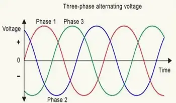
In North American electrical power systems operating at 60 hertz, harmonics in power appear as integer multiples of the fundamental frequency that distort voltage and current waveforms. Linear loads draw sinusoidal current and preserve waveform symmetry, but nonlinear devices such as variable frequency drives and switched mode power supplies inject current components that stress electrical equipment and sensitive electronic equipment. These distortion mechanisms propagate through the electrical system and can manifest as broader power quality issues when impedance conditions amplify specific harmonic orders.
Voltage THD limits are evaluated at the interface between the facility and the utility. Compliance determination requires structured Power Quality Monitoring capable of capturing steady state distortion and event driven variation across operating conditions.
Internal distribution buses can experience distortion levels significantly higher than those measured at the point of common coupling. A facility may remain contractually compliant at the utility interface while internal 480 V buses exceed 8 percent voltage THD, masking localized transformer heating and capacitor stress that never appears in PCC reporting.
A deployment tradeoff emerges between operating close to harmonic limits to maximize equipment utilization and maintaining conservative distortion margins to absorb impedance variation. Facilities that run at 4.5 percent voltage THD under normal configuration may exceed 5 percent when short circuit capacity decreases during maintenance switching.
Distortion compliance, therefore, cannot be modeled as a static calculation. It must incorporate system stiffness, nonlinear load growth, and distributed generation variability. The threshold discipline problem is to define the acceptable level of distortion before contractual exposure and equipment stress increase.
Harmonic currents increase copper losses and stray flux heating in transformers. In documented industrial measurements, transformer hot spot temperatures rose by 6-10 °C when voltage THD increased from 3% to 8% under constant load. That temperature rise accelerates insulation aging and reduces expected service life.
Facilities that rely solely on fundamental frequency loading estimates may underestimate the true thermal stress. Harmonic distortion distorts apparent loading relationships described in Apparent Power, especially when distorted current inflates RMS values without a proportional increase in real power.
The cascading consequence is cumulative. Elevated heating reduces insulation margins, increasing failure probability and potentially triggering unplanned outages. If distortion driven heating causes transformer derating or replacement, harmonic tolerance becomes a capital planning variable rather than a maintenance statistic.
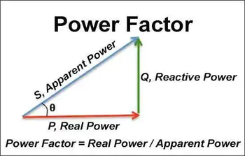
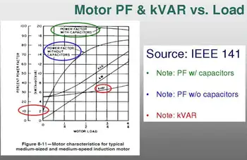
Harmonic governance becomes more complex when reactive compensation is introduced. Capacitor banks installed for Power Factor Correction can shift system resonance frequency into alignment with dominant harmonic orders.
When resonance aligns with the fifth or seventh harmonic, current magnification occurs. Instead of reducing losses, the capacitor bank amplifies distortion. Improperly selected Power Factor Correction Capacitor ratings without detuning reactors can accelerate dielectric stress and cause premature failure.
The tradeoff is clear. Aggressive reactive compensation reduces utility penalties but increases sensitivity to harmonic amplification. Conservative compensation reduces resonance risk but may leave the power factor below contractual targets.
Think you know Power Quality? Take our quick, interactive quiz and test your knowledge in minutes.
Harmonic distortion alters waveform shape and can affect current transformer saturation and relay pickup characteristics. Protection elements calibrated for sinusoidal conditions may misinterpret distorted waveforms during motor starts or fault conditions with elevated harmonic content.
This operational edge case becomes critical where high drive penetration coincides with low system stiffness. False trips during process operation introduce reliability risk and production loss. Conversely, a delayed trip due to waveform distortion can extend fault duration.
Verification requires a calibrated Power Quality Analyzer capable of harmonic spectrum logging and time synchronized waveform capture. Measurement uncertainty itself becomes a model constraint. If logging intervals are too coarse or the harmonic resolution is insufficient, compliance determination may be inconclusive.
Power quality and harmonics management ultimately centers on defining an acceptable distortion margin. Operating consistently below 3 percent voltage THD provides a buffer against changes in impedance and load growth. Operating near 5 percent maximizes infrastructure utilization but narrows the safety margin.
The unresolved boundary is strategic. How much distortion headroom is required to protect transformer life, prevent capacitor resonance, and avoid relay misoperation under future load expansion and distributed energy integration?
If compliance metrics are tied to contractual obligations or executive reliability targets, distortion governance becomes a board level decision variable. The engineering obligation is not the elimination of harmonics. It is disciplined control of distortion thresholds before thermal acceleration, resonance amplification, and protection instability convert into avoidable failure.
Explore 50+ live, expert-led electrical training courses –