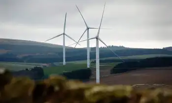
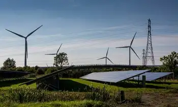
ABB has won a $125 million order to connect a wind farm 30 kilometers off the Belgian coast to the mainland grid, a further step by the Swiss engineer to capitalize on the push for green technologies.
Scheduled to begin service in 2013, the Belgian wind farm was expected to generate 1,000 gigawatt-hours of electricity per year — equivalent to the annual consumption of 600,000 people in Belgium, ABB said.
The order was placed by Belgian company C-Power NV.
In July, ABB, which produces equipment for utility companies, received its largest-ever such transmission order, a $700 million order to connect North Sea wind farms to the German grid.
US Power Grid Blackouts highlight aging infrastructure, rising outages, and declining reliability per DOE and NERC data, with weather-driven failures, cyberattack risk, and underinvestment stressing utilities, transmission lines, and modernization efforts.
Key Points
US power grid blackouts are outages caused by aging grid assets, severe weather, and cyber threats reducing reliability.
✅ DOE and NERC data show rising outage frequency and duration.
✅ Weather now drives 68-73% of major failures since 2008.
✅ Modernization, hardening, and cybersecurity investments are critical.
The United States power grid has more blackouts than any other country in the developed world, according to new data and U.S. blackout warnings that spotlight the country’s aging and unreliable electric system.
The data by the Department of Energy (DOE) and the North American Electric Reliability Corporation (NERC) shows that Americans face more power grid failures lasting at least an hour than residents of other developed nations.
And it’s getting worse.
Going back three decades, the US grid loses power 285 percent more often than it did in 1984, when record keeping began, International Business Times reported. The power outages cost businesses in the United States as much as $150 billion per year, according to the Department of Energy.
Customers in Japan lose power for an average of 4 minutes per year, as compared to customers in the US upper Midwest (92 minutes) and upper Northwest (214), University of Minnesota Professor Massoud Amin told the Times. Amin is director of the Technological Leadership Institute at the school.
#google#
The grid is becoming less dependable each year, he said.
“Each one of these blackouts costs tens of hundreds of millions, up to billions, of dollars in economic losses per event,” Amin said. “… We used to have two to five major weather events per year [that knocked out power], from the ‘50s to the ‘80s. Between 2008 and 2012, major outages caused by weather, reflecting extreme weather trends, increased to 70 to 130 outages per year. Weather used to account for about 17 to 21 percent of all root causes. Now, in the last five years, it’s accounting for 68 to 73 percent of all major outages.”
As previously reported by Off The Grid News, the power grid received a “D+” grade on its power grid report card from the American Society of Civil Engineers (ASCE) in 2013. The power grid grade card rating means the energy infrastructure is in “poor to fair condition and mostly below standard, with many elements approaching the end of their service life.” It further means a “large portion of the system exhibits significant deterioration” with a “strong risk of failure.”
“America relies on an aging electrical grid and pipeline distribution systems, some of which originated in the 1880s,” the 2013 ASCE report read. “Investment in power transmission has increased since 2005, but ongoing permitting issues, weather events, and limited maintenance have contributed to an increasing number of failures and power interruptions.”
As The Times noted, the US power grid as it exists today was built shortly after World War II, with the design dating back to Thomas Edison. While Edison was a genius, he and his contemporaries could not have envisioned all the strains the modern world would place upon the grid and the multitude of tech gadgets many Americans treat as an extension of their body. While the drain on the grid has advanced substantially, the infrastructure itself has not.
There are approximately 5 million miles of electrical transmission lines throughout the United States, and thousands of power generating plants dot the landscape. The electrical grid is managed by a group of 3,300 different utilities and serve about 150 million customers, The Times said. The entire power grid system is currently valued at $876 billion.
Former Department of Homeland Security Secretary Janet Napolitano once said that a power grid cyber attack is a matter of “when” not “if,” as Russians hacked utilities incidents have shown.
Global Energy Electrification drives IEA targets as smart grids, storage, EVs, and demand-side management scale. Paris Agreement-aligned policies and innovation accelerate decarbonization, enabling flexible, low-carbon power systems and net-zero pathways by 2060.
Key Points
A shift to electricity across sectors via smart grids, storage, EVs, and policy to cut CO2 and improve energy security.
✅ Aligns with IEA pathways and Paris Agreement goals.
✅ Drives EV adoption, building efficiency, and net-zero by 2060.
The global energy system is changing, with European electricity market trends highlighting rapid shifts. More people are connecting to the grid as living standards improve around the world. Demand for consumer appliances and electronic devices is rising. New and innovative transportation technologies, such as electric vehicles and autonomous cars are also boosting power demand.
The International Energy Agency's latest report on energy technologies outlines how these and other trends as well as technological advances play out in the next four decades to reshape the global energy sector.
Energy Technology Perspectives 2017 (ETP) highlights that decisive policy actions and market signals will be needed to drive technological development and benefit from higher electrification around the world. Investments in stronger and smarter infrastructure, including transmission capacity, storage capacity and demand side management technologies such as demand response programs are necessary to build efficient, low-carbon, integrated, flexible and robust energy system.
Still, current government policies are not sufficient to achieve long-term global climate goals, according to the IEA analysis, and warnings about falling global energy investment suggest potential supply risks as well. Only 3 out of 26 assessed technologies remain “on track” to meet climate objectives, according to the ETP’s Tracking Clean Energy Progress report. Where policies have provided clean signals, progress has been substantial. However, many technology areas suffer from inadequate policy support.
"As costs decline, we will need a sustained focus on all energy technologies to reach long-term climate targets," said IEA Executive Director Dr Fatih Birol. "Some are progressing, but too few are on track, and this puts pressure on others. It is important to remember that speeding the rate of technological progress can help strengthen economies, boost energy security while also improving energy sustainability."
ETP 2017’s base case scenario, known as the Reference Technology Scenario (RTS), takes into account existing energy and climate commitments, including those made under the Paris Agreement. Another scenario, called 2DS, shows a pathway to limit the rise of global temperature to 2ºC, and finds the global power sector could reach net-zero CO2 emissions by 2060.
A second decarbonisation scenario explores how much available technologies and those in the innovation pipeline could be pushed to put the energy sector on a trajectory beyond 2DS. It shows how the energy sector could become carbon neutral by 2060 if known technology innovations were pushed to the limit. But to do so would require an unprecedented level of policy action and effort from all stakeholders.
Looking at specific sectors, ETP 2017 finds that buildings could play a major role in supporting the energy system transformation. High-efficiency lighting, cooling and appliances could save nearly three-quarters of today’s global electricity demand between now and 2030 if deployed quickly. Doing so would allow a greater electrification of the energy system that would not add burdens on the system. In the transportation system, electrification also emerges as a major low-carbon pathway, with clean grids and batteries becoming key areas to watch in deployment.
The report finds that regardless of the pathway chosen, policies to support energy technology innovation at all stages, from research to full deployment, alongside evolving utility trends that operators need to watch, will be critical to reap energy security, environmental and economic benefits of energy system transformations. It also suggests that the most important challenge for energy policy makers will be to move away from a siloed perspective towards one that enables systems integration.
Cape Town Renewable Energy Plan targets 450+ MW via solar, wind, and battery storage, cutting Eskom reliance, lowering greenhouse gas emissions, stabilizing electricity prices, and boosting grid resilience through municipal procurement, PPAs, and city-owned plants.
Key Points
A municipal plan to procure over 450 MW, cut Eskom reliance, stabilize prices, and reduce Cape Town emissions.
✅ Up to 150 MW from private plants within the city
✅ 300 MW to be purchased from outside Cape Town later
✅ City financing 100-200 MW of its own generation
Cape Town is seeking to secure more than 450 megawatts of power from renewable sources to cut reliance on state power utility Eskom Holdings SOC Ltd., where wind procurement cuts were considered during lockdown, and reduce greenhouse gas emissions.
South Africa’s second-biggest city is looking at a range of options, including geothermal exploration in comparable markets, and expects the bulk of the electricity to be generated from solar plants, Kadri Nassiep, the city’s executive director of energy and climate change, said in an interview.
On July 14 the city of 4.6 million people released a request for information to seek funding to build its own plants. This month or next it will seek proposals for the provision of as much as 150 megawatts from privately owned plants, largely solar additions, to be built and operated within the city, he said. As much as 300 megawatts may also be purchased at a later stage from plants outside of Cape Town, according to Nassiep.
The city could secure finance to build 100 to 200 megawatts of its own generation capacity, Nassiep said. “We realized that it is important for the city to be more in control around the pricing of the power,” he added.
Power Outages
Cape Town’s foray into the securing of power from sources other than Eskom comes after more than a decade of intermittent electricity outages, while elsewhere in Africa coal projects face scrutiny from lenders, because the utility can’t meet national demand. The government last year said municipalities could find alternative suppliers.
Earlier this month Ethekwini, the municipal area that includes the city of Durban, issued a request for information for the provision of 400 megawatts of power, similar to BC Hydro’s call for power driven by EV uptake.
The City of Johannesburg will in September seek information and proposals for the construction of a 150-megawatt solar plant, reflecting moves like Ontario’s new wind and solar procurements to tackle supply gaps, 50 megawatts of rooftop solar panels and the refurbishment of an idle gas-fired plant that could generate 20 megawatts, it said in June. It will also seek information for the installation of 100 megawatts of battery storage.
Cape Town, which uses a peak of 1,800 megawatts of electricity in winter, hopes to start generating some of its own power next year, aligning with SaskPower’s 2030 renewables plan seen in Canada, according to a statement that accompanied its request for financing proposals.
Foote Creek I Wind Farm Repowering upgrades Wyoming turbines with new nacelles, towers, and blades, cutting 68 units to 12 while sustaining 41.6 MW, under PacifiCorp and Rocky Mountain Power's Energy Vision 2020 plan.
Key Points
Replacement at Foote Creek Rim I, cutting to 12 turbines while sustaining about 41.6 MW using modern 2-4.2 MW units.
✅ 12 turbines replace 68, output steady near 41.6 MW
✅ New nacelles, towers, blades; taller 500 ft turbines
✅ Part of PacifiCorp Energy Vision 2020 and Gateway West
A Wyoming utility company has filed a permit to replace its first wind farm—originally commissioned in 1998, composed of over 65 turbines—amid new gas capacity competing with nuclear in Ohio, located at Foote Creek Rim I. The replacement would downsize the number of turbines to 12, which would still generate roughly the same energy output.
According to the Star Tribune, PacifiCorp’s new installation would involve new nacelles, new towers and new blades. The permit was filed with Carbon County.
New WY Wind Farm
The replacement wind turbines will stand more than twice as tall as the old: Those currently installed stand 200 feet tall, whereas their replacements will tower closer to 500 feet. Though this move is part of the company’s overall plan to expand its state wind fleet as some utilities respond to declining coal returns in the Midwest, the work going into the Foote Creek site is somewhat special, noted David Eskelsen, spokesperson for Rocky Mountain Power, the western arm of PacifiCorp.
“Foote Creek I repowering is somewhat different from the repowering projects announced in the (Energy Vision) 2020 initiative,” he said. “Foote Creek is a complete replacement of the existing 68 foundations, towers, turbine nacelles and rotors (blades).”
Currently, the turbines at Foote Creek have 600 kilowatts capacity each; the replacements’ maximum production ranges from 2 megawatts to 4.2 megawatts each, with the total output remaining steady at 41.4 megawatts, a scale similar to a 30-megawatt wind expansion in Eastern Kings, though there will be a slight capacity increase to 41.6 megawatts, according to the Star Tribune.
As part of the wind farm repowering initiative, PacifiCorp is to become full owner and operator of the Foote Creek site. When the farm was originally built, an Oregon-based water and electric board was 21 percent owner; 37 percent of the project’s output was tied into a contract with the Bonneville Power Administration.
Otherwise, PacifiCorp is moving to further expand its state wind fleet in line with initiatives like doubling renewable electricity by 2030 in Saskatchewan, with the addition of three new wind farms—to be located in Carbon, Albany and Converse counties—which may add up to 1,150 megawatts of power.
According to PacifiCorp, the company has more than 1,000 megawatts of owned wind generation capability, along with long-term purchase agreements for more than 600 megawatts from other wind farms owned by other entities. Energy Vision 2020 refers to a $3.5 billion investment and company move that is looking to upgrade the company's existing wind fleet with newer technology, adding 1,150 megawatts of new wind resources by 2020 and a a new 140-mile Gateway West transmission segment in Wyoming, comparable to a transmission project in Missouri just energized.
Boeing 787 More-Electric Architecture replaces pneumatics with bleedless pressurization, VFSG starter-generators, electric brakes, and heated wing anti-ice, leveraging APU, RAT, batteries, and airport ground power for efficient, redundant electrical power distribution.
Key Points
An integrated, bleedless electrical system powering start, pressurization, brakes, and anti-ice via VFSGs, APU and RAT.
✅ VFSGs start engines, then generate 235Vac variable-frequency power
✅ Bleedless pressurization, electric anti-ice improve fuel efficiency
✅ Electric brakes cut hydraulic weight and simplify maintenance
The 787 Dreamliner is different to most commercial aircraft flying the skies today. On the surface it may seem pretty similar to the likes of the 777 and A350, but get under the skin and it’s a whole different aircraft.
When Boeing designed the 787, in order to make it as fuel efficient as possible, it had to completely shake up the way some of the normal aircraft systems operated. Traditionally, systems such as the pressurization, engine start and wing anti-ice were powered by pneumatics. The wheel brakes were powered by the hydraulics. These essential systems required a lot of physical architecture and with that comes weight and maintenance. This got engineers thinking.
What if the brakes didn’t need the hydraulics? What if the engines could be started without the pneumatic system? What if the pressurisation system didn’t need bleed air from the engines? Imagine if all these systems could be powered electrically… so that’s what they did.
Power sources
The 787 uses a lot of electricity. Therefore, to keep up with the demand, it has a number of sources of power, much as grid operators track supply on the GB energy dashboard to balance loads. Depending on whether the aircraft is on the ground with its engines off or in the air with both engines running, different combinations of the power sources are used.
Engine starter/generators
The main source of power comes from four 235Vac variable frequency engine starter/generators (VFSGs). There are two of these in each engine. These function as electrically powered starter motors for the engine start, and once the engine is running, then act as engine driven generators.
The generators in the left engine are designated as L1 and L2, the two in the right engine are R1 and R2. They are connected to their respective engine gearbox to generate electrical power directly proportional to the engine speed. With the engines running, the generators provide electrical power to all the aircraft systems.
APU starter/generators
In the tail of most commercial aircraft sits a small engine, the Auxiliary Power Unit (APU). While this does not provide any power for aircraft propulsion, it does provide electrics for when the engines are not running.
The APU of the 787 has the same generators as each of the engines — two 235Vac VFSGs, designated L and R. They act as starter motors to get the APU going and once running, then act as generators. The power generated is once again directly proportional to the APU speed.
The APU not only provides power to the aircraft on the ground when the engines are switched off, but it can also provide power in flight should there be a problem with one of the engine generators.
Battery power
The aircraft has one main battery and one APU battery. The latter is quite basic, providing power to start the APU and for some of the external aircraft lighting.
The main battery is there to power the aircraft up when everything has been switched off and also in cases of extreme electrical failure in flight, and in the grid context, alternatives such as gravity power storage are being explored for long-duration resilience. It provides power to start the APU, acts as a back-up for the brakes and also feeds the captain’s flight instruments until the Ram Air Turbine deploys.
Ram air turbine (RAT) generator
When you need this, you’re really not having a great day. The RAT is a small propeller which automatically drops out of the underside of the aircraft in the event of a double engine failure (or when all three hydraulics system pressures are low). It can also be deployed manually by pressing a switch in the flight deck.
Once deployed into the airflow, the RAT spins up and turns the RAT generator. This provides enough electrical power to operate the captain’s flight instruments and other essentials items for communication, navigation and flight controls.
External power
Using the APU on the ground for electrics is fine, but they do tend to be quite noisy. Not great for airports wishing to keep their noise footprint down. To enable aircraft to be powered without the APU, most big airports will have a ground power system drawing from national grids, including output from facilities such as Barakah Unit 1 as part of the mix. Large cables from the airport power supply connect 115Vac to the aircraft and allow pilots to shut down the APU. This not only keeps the noise down but also saves on the fuel which the APU would use.
The 787 has three external power inputs — two at the front and one at the rear. The forward system is used to power systems required for ground operations such as lighting, cargo door operation and some cabin systems. If only one forward power source is connected, only very limited functions will be available.
The aft external power is only used when the ground power is required for engine start.
Circuit breakers
Most flight decks you visit will have the back wall covered in circuit breakers — CBs. If there is a problem with a system, the circuit breaker may “pop” to preserve the aircraft electrical system. If a particular system is not working, part of the engineers procedure may require them to pull and “collar” a CB — placing a small ring around the CB to stop it from being pushed back in. However, on the 787 there are no physical circuit breakers. You’ve guessed it, they’re electric.
Within the Multi Function Display screen is the Circuit Breaker Indication and Control (CBIC). From here, engineers and pilots are able to access all the “CBs” which would normally be on the back wall of the flight deck. If an operational procedure requires it, engineers are able to electrically pull and collar a CB giving the same result as a conventional CB.
Not only does this mean that the there are no physical CBs which may need replacing, it also creates space behind the flight deck which can be utilised for the galley area and cabin.
A normal flight
While it’s useful to have all these systems, they are never all used at the same time, and, as the power sector’s COVID-19 mitigation strategies showed, resilience planning matters across operations. Depending on the stage of the flight, different power sources will be used, sometimes in conjunction with others, to supply the required power.
On the ground
When we arrive at the aircraft, more often than not the aircraft is plugged into the external power with the APU off. Electricity is the blood of the 787 and it doesn’t like to be without a good supply constantly pumping through its system, and, as seen in NYC electric rhythms during COVID-19, demand patterns can shift quickly. Ground staff will connect two forward external power sources, as this enables us to operate the maximum number of systems as we prepare the aircraft for departure.
Whilst connected to the external source, there is not enough power to run the air conditioning system. As a result, whilst the APU is off, air conditioning is provided by Preconditioned Air (PCA) units on the ground. These connect to the aircraft by a pipe and pump cool air into the cabin to keep the temperature at a comfortable level.
APU start
As we near departure time, we need to start making some changes to the configuration of the electrical system. Before we can push back , the external power needs to be disconnected — the airports don’t take too kindly to us taking their cables with us — and since that supply ultimately comes from the grid, projects like the Bruce Power upgrade increase available capacity during peaks, but we need to generate our own power before we start the engines so to do this, we use the APU.
The APU, like any engine, takes a little time to start up, around 90 seconds or so. If you remember from before, the external power only supplies 115Vac whereas the two VFSGs in the APU each provide 235Vac. As a result, as soon as the APU is running, it automatically takes over the running of the electrical systems. The ground staff are then clear to disconnect the ground power.
If you read my article on how the 787 is pressurised, you’ll know that it’s powered by the electrical system. As soon as the APU is supplying the electricity, there is enough power to run the aircraft air conditioning. The PCA can then be removed.
Engine start
Once all doors and hatches are closed, external cables and pipes have been removed and the APU is running, we’re ready to push back from the gate and start our engines. Both engines are normally started at the same time, unless the outside air temperature is below 5°C.
On other aircraft types, the engines require high pressure air from the APU to turn the starter in the engine. This requires a lot of power from the APU and is also quite noisy. On the 787, the engine start is entirely electrical.
Power is drawn from the APU and feeds the VFSGs in the engines. If you remember from earlier, these fist act as starter motors. The starter motor starts the turn the turbines in the middle of the engine. These in turn start to turn the forward stages of the engine. Once there is enough airflow through the engine, and the fuel is igniting, there is enough energy to continue running itself.
After start
Once the engine is running, the VFSGs stop acting as starter motors and revert to acting as generators. As these generators are the preferred power source, they automatically take over the running of the electrical systems from the APU, which can then be switched off. The aircraft is now in the desired configuration for flight, with the 4 VFSGs in both engines providing all the power the aircraft needs.
As the aircraft moves away towards the runway, another electrically powered system is used — the brakes. On other aircraft types, the brakes are powered by the hydraulics system. This requires extra pipe work and the associated weight that goes with that. Hydraulically powered brake units can also be time consuming to replace.
By having electric brakes, the 787 is able to reduce the weight of the hydraulics system and it also makes it easier to change brake units. “Plug in and play” brakes are far quicker to change, keeping maintenance costs down and reducing flight delays.
In-flight
Another system which is powered electrically on the 787 is the anti-ice system. As aircraft fly though clouds in cold temperatures, ice can build up along the leading edge of the wing. As this reduces the efficiency of the the wing, we need to get rid of this.
Other aircraft types use hot air from the engines to melt it. On the 787, we have electrically powered pads along the leading edge which heat up to melt the ice.
Not only does this keep more power in the engines, but it also reduces the drag created as the hot air leaves the structure of the wing. A double win for fuel savings.
Once on the ground at the destination, it’s time to start thinking about the electrical configuration again. As we make our way to the gate, we start the APU in preparation for the engine shut down. However, because the engine generators have a high priority than the APU generators, the APU does not automatically take over. Instead, an indication on the EICAS shows APU RUNNING, to inform us that the APU is ready to take the electrical load.
Shutdown
With the park brake set, it’s time to shut the engines down. A final check that the APU is indeed running is made before moving the engine control switches to shut off. Plunging the cabin into darkness isn’t a smooth move. As the engines are shut down, the APU automatically takes over the power supply for the aircraft. Once the ground staff have connected the external power, we then have the option to also shut down the APU.
However, before doing this, we consider the cabin environment. If there is no PCA available and it’s hot outside, without the APU the cabin temperature will rise pretty quickly. In situations like this we’ll wait until all the passengers are off the aircraft until we shut down the APU.
Once on external power, the full flight cycle is complete. The aircraft can now be cleaned and catered, ready for the next crew to take over.
Bottom line
Electricity is a fundamental part of operating the 787. Even when there are no passengers on board, some power is required to keep the systems running, ready for the arrival of the next crew. As we prepare the aircraft for departure and start the engines, various methods of powering the aircraft are used.
The aircraft has six electrical generators, of which only four are used in normal flights. Should one fail, there are back-ups available. Should these back-ups fail, there are back-ups for the back-ups in the form of the battery. Should this back-up fail, there is yet another layer of contingency in the form of the RAT. A highly unlikely event.
The 787 was built around improving efficiency and lowering carbon emissions whilst ensuring unrivalled levels safety, and, in the wider energy landscape, perspectives like nuclear beyond electricity highlight complementary paths to decarbonization — a mission it’s able to achieve on hundreds of flights every single day.
Schott Green Electricity CPPA secures renewable energy via a solar park in Schleswig-Holstein, supporting decarbonization in German glass manufacturing; the corporate PPA with ane.energy delivers about 14.5 GWh annually toward climate-neutral production by 2030.
Key Points
Corporate PPA for 14.5 GWh solar in Germany, cutting Schott plant emissions and advancing climate-neutral operations.
✅ 14.5 GWh solar from Schleswig-Holstein via ane.energy
✅ Powers Mainz HQ and plants in Gr FCnenplan, Mitterteich, Landshut
✅ Two-year CPPA covers ~5% of Schott's German electricity needs
Schott, a leading specialty glass manufacturer, is advancing its sustainability initiatives in step with Germany's energy transition by integrating green electricity into its operations. Through a Corporate Power Purchase Agreement (CPPA) with green energy specialist ane.energy, Schott aims to significantly reduce its carbon footprint and move closer to its goal of climate-neutral production by 2030.
Transition to Renewable Energy
As of February 2025, amid a German renewables milestone for the power sector, Schott has committed to sourcing approximately 14.5 gigawatt-hours of clean energy annually from a solar park in Schleswig-Holstein, Germany. This renewable energy will power Schott's headquarters in Mainz and its plants in Grünenplan, Mitterteich, and Landshut. The CPPA covers about 5% of the company's annual electricity needs in Germany and is initially set for a two-year term, reflecting lessons from extended nuclear power during recent supply challenges.
Strategic Implementation
To achieve climate-neutral production by 2030, Schott is focusing on transitioning from gas to electricity sourced from renewable sources like photovoltaics, alongside complementary pathways such as hydrogen-ready power plants being developed nationally. Operating a single melting tank requires energy equivalent to the annual consumption of up to 10,000 single-family homes. Therefore, Schott has strategically selected suitable plants for this renewable energy supply to meet its substantial energy requirements.
Industry Leadership
Schott's collaboration with ane.energy demonstrates the company's commitment to sustainability and its proactive approach to integrating renewable energy into industrial operations. This partnership not only supports Schott's decarbonization goals but also sets a precedent for other manufacturers in the glass industry to adopt green energy solutions, mirroring advances like green hydrogen steel in heavy industry.
Schott's initiative to power its German glass plants with green electricity underscores the company's dedication to environmental responsibility and its strategic efforts to achieve climate-neutral production by 2030, aligning with the national coal and nuclear phaseout underway. This move reflects a broader trend in the manufacturing sector toward sustainable practices and the adoption of renewable energy sources, even as debates continue over a possible nuclear phaseout U-turn in Germany.