Proposed underground power line could bring Iowa wind turbine electricity to Chicago


chicago wind electricity

Arc Flash Training CSA Z462 - Electrical Safety Essentials

Our customized live online or in‑person group training can be delivered to your staff at your location.
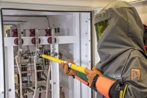
  • Live Online
  • 6 hours Instructor-led
  • Group Training Available
Regular Price:
$249
Coupon Price:
$199
Reserve Your Seat Today

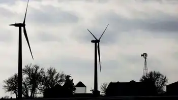
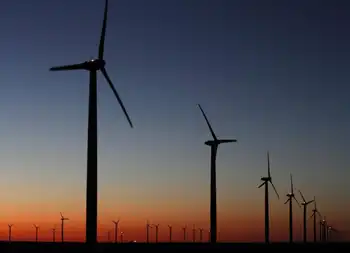
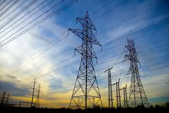
SOO Green Underground Transmission Line proposes an HVDC corridor buried along Canadian Pacific railroad rights-of-way to deliver Iowa wind energy to Chicago, enhance grid interconnection, and reduce landowner disruption from new overhead lines.


Key Points

A proposed HVDC project burying lines along a railroad to move Iowa wind power to Chicago and link two grids.

✅ HVDC link from Mason City, IA, to Plano, IL

✅ Buried in Canadian Pacific railroad right-of-way

✅ Connects MISO and PJM grids for renewable exchange


The company behind a proposed underground transmission line that would carry electricity generated mostly by wind turbines in Iowa to the Chicago area said Monday that the $2.5 billion project could be operational in 2024 if regulators approve it, reflecting federal transmission funding trends seen recently.

Direct Connect Development Co. said it has lined up three major investors to back the project. It plans to bury the transmission line in land that runs along existing Canadian Pacific railroad tracks, hopefully reducing the disruption to landowners. It's not unusual for pipelines or fiber optic lines to be buried along railroad tracks in the land the railroad controls.

CEO Trey Ward said he "believes that the SOO Green project will set the standard regarding how transmission lines are developed and constructed in the U.S."

A similar proposal from a different company for an overhead transmission line was withdrawn in 2016 after landowners raised concerns, even as projects like the Great Northern Transmission Line advanced in the region. That $2 billion Rock Island Clean Line was supposed to run from northwest Iowa into Illinois.

The new proposed line, which was first announced in 2017, would run from Mason City, Iowa, to Plano, Ill., a trend echoed by Canadian hydropower to New York projects. The investors announced Monday were Copenhagen Infrastructure Partners, Jingoli Power and Siemens Financial Services.

The underground line would also connect two different regional power operating grids, as seen with U.S.-Canada cross-border transmission approvals in recent years, which would allow the transfer of renewable energy back and forth between customers and producers in the two regions.

More than 36 percent of Iowa's electricity comes from wind turbines across the state.

Jingoli Power CEO Karl Miller said the line would improve the reliability of regional power operators and benefit utilities and corporate customers in Chicago, even amid debates such as Hydro-Quebec line opposition in the Northeast.


Related News

Related News

Biggest offshore windfarm to start UK supply this week

Hornsea One Offshore Wind Farm delivers first power to the UK grid, scaling renewable energy with 1.2GW capacity, giant offshore turbines, and Yorkshire coast infrastructure to replace delayed nuclear and cut fossil fuel emissions.


Key Points

Hornsea One Offshore Wind Farm is a 1.2GW UK project delivering offshore renewable power to about 1 million homes.

✅ 174 turbines over 407 km2; Siemens Gamesa supply chain in the UK

✅ 1.2GW capacity can power ~1m homes; phases scale with 10MW+ turbines

✅ Supports UK grid, replaces delayed nuclear, cuts fossil generation


An offshore windfarm on the Yorkshire coast that will dwarf the world’s largest when completed is to supply its first power to the UK electricity grid this week, mirroring advances in tidal electricity projects delivering to the grid as well.

The Danish developer Ørsted, which has installed the first of 174 turbines at Hornsea One, said it was ready to step up its plans and fill the gap left by failed nuclear power schemes.

The size of the project takes the burgeoning offshore wind power sector to a new scale, on a par with conventional fossil fuel-fired power stations.

Hornsea One will cover 407 square kilometres, five times the size of the nearby city of Hull. At 1.2GW of capacity it will power 1m homes, making it about twice as powerful as today’s biggest offshore windfarm once it is completed in the second half of this year.

“The ability to generate clean electricity offshore at this scale is a globally significant milestone at a time when urgent action needs to be taken to tackle climate change,” said Matthew Wright, UK managing director of Ørsted, the world’s biggest offshore windfarm builder.

The power station is only the first of four planned in the area, with a green light and subsidies already awarded to a second stage due for completion in the early 2020s, and interest from Japanese utilities underscoring growing investor appetite.

The first two phases will use 7MW turbines, which are taller than London’s Gherkin building.

But the latter stages of the Hornsea development could use even more powerful, 10MW-plus turbines. Bigger turbines will capture more of the energy from the wind and should lower costs by reducing the number of foundations and amount of cabling firms need to put into the water, with developers noting that offshore wind can compete with gas in the U.S. as costs fall.

Henrik Poulsen, Ørsted’s chief executive, said he was in close dialogue with major manufacturers to use the new generation of turbines, some of which are expected to approach the height of the Shard in London, the tallest building in the EU.

The UK has a great wind resource and shallow enough seabed to exploit it, and could even “power most of Europe if it [the UK] went to the extreme with offshore”, he said.

Offshore windfarms could help ministers fill the low carbon power gap created by Hitachi and Toshiba scrapping nuclear plants, the executive suggested. “If nuclear should play less of a role than expected, I believe offshore wind can step up,” he said.

New nuclear projects in Europe had been “dramatically delayed and over budget”, he added, in comparison to “the strong track record for delivering offshore [wind]”.

The UK and Germany installed 85% of new offshore wind power capacity in the EU last year, according to industry data, with wind leading power across several markets. The average power rating of the turbines is getting bigger too, up 15% in 2018.

The turbines for Hornsea One are built and shipped from Siemens Gamesa’s factory in Hull, part of a web of UK-based suppliers that has sprung up around the growing sector, such as Prysmian UK's land cables supporting grid connections.

Around half of the project’s transition pieces, the yellow part of the structure that connects the foundation to the tower, are made in Teeside. Many of the towers themselves are made by a firm in Campbeltown in the Scottish highlands. Altogether, about half of the components for the project are made in the UK.

Ørsted is not yet ready to bid for a share of a £60m pot of further offshore windfarm subsidies, to be auctioned by the government this summer, but expects the price to reach even more competitive levels than those seen in 2017.

Like other international energy companies, Ørsted has put in place contingency planning in event of a no-deal Brexit – but the hope is that will not come to pass. “We want a Brexit deal that will facilitate an orderly transition out of the union,” said Poulsen.


Related News

View more

Ontario announces SMR plans to four reactors at Darlington

Ontario Darlington SMR Expansion advances four GE Hitachi BWRX-300 reactors with OPG, adding 1,200 MW of baseload nuclear power to support electrification, grid reliability, and clean energy growth across Ontario and Saskatchewan.


Key Points

Plan to build four BWRX-300 SMRs at Darlington, delivering 1,200 MW of clean, reliable baseload power under OPG.

✅ Four GE Hitachi BWRX-300 units, 1,200 MW total

✅ Shared infrastructure cuts costs and timelines

✅ Supports electrification, grid reliability, net zero


The day after Ontario announced it would be building an additional 4,800 megawatts of nuclear reactors at Bruce Nuclear Generating Station, the province announced it would be dramatically expanding its planned rollout of small modular reactors at its Darlington Nuclear Generating Station, and confirmed plans to refurbish Pickering B as part of its broader strategy.

Ontario Power Generation OPG was always going to be the first to build the GE-Hitachi BWRX-300 small modular reactor SMR, with the U.S.’s Tennessee Valley Authority among others like SaskPower and several European nations following suit. But the OPG was originally going to build just one. On July 7, OPG and the Province of Ontario announced they would be bumping that up to four units of the BWRX-300.

The Ontario government is working with Ontario Power Generation (OPG) to commence planning and licensing for three additional small modular reactors (SMRs), for a total of four SMRs at the Darlington nuclear site. Once deployed, these four units would produce a total 1,200 megawatts (MW) of electricity, equivalent to powering 1.2 million homes, helping to meet increasing demand from electrification and fuel the province’s strong economic growth, the Ontario Ministry of Energy said in a release.

“Our government’s open for business approach has led to unprecedented investments across the province — from electric vehicles and battery manufacturing to critical minerals to green steel,” said Todd Smith, Minister of Energy. “Expanding Ontario’s world-leading SMR program will ensure we have the reliable, affordable and clean electricity we need to power the next major international investment, the new homes we are building and industries as they grow and electrify.”

For the first time since 2005, Ontario’s electricity demand is rising. While the government has implemented its plan to meet rising electricity demand this decade, the experts at Ontario’s Independent Electricity System Operator have recommended the province advance new nuclear generation and pursue life-extension at Pickering NGS to provide reliable, baseload power to meet increasing electricity needs in the 2030s and beyond.

Subject to Ontario Government and Canadian Nuclear Safety Commission (CNSC) regulatory approvals on construction, the additional SMRs could come online between 2034 and 2036. That is the same timeframe that SaskPower is looking at for its first, and possibly second, units.

The initial unit is expected to go online in 2028 following Ontario’s first SMR groundbreaking at Darlington.

The Darlington site, which already hosts four reactors, was originally considered for an expansion of “large nuclear,” which is why OPG was already well on its way for site approvals of additional nuclear power generation. The plan changed to one, singular, SMR. Now that has been updated to four.

The announcement has significant impact on Saskatchewan, and its plans to build four of its own SMRs. The timing would allow Ontario Power Generation to apply learnings from the construction of the first unit to deliver cost savings on subsequent units. This is also the strategy SaskPower is following – allow Ontario to build the first, then learn from that experience.

Building multiple units will also allow common infrastructure such as cooling water intake, transmission connection and control room to be utilized by all four units instead of just one, reducing costs even further, the Ministry said.

“A fleet of SMRs at the Darlington New Nuclear Site is key to meeting growing electricity demands and net zero goals,” said Ken Hartwick, OPG President and CEO. “OPG has proven its large nuclear project expertise through the on-time, on budget Darlington Refurbishment project. By taking a similar approach to building a fleet of SMRs, we will deliver cost and schedule savings, and power 1.2 million homes from this site by the mid-2030s.”

The Darlington SMR project is situated on the traditional and treaty territories of the seven Williams Treaties First Nations and is also located within the traditional territory of the Huron Wendat peoples. OPG is actively engaging and consulting with potentially impacted Indigenous communities, including exploring economic opportunities in the Darlington SMR project such as commercial participation and employment.

The Ministry noted, “Ontario’s robust nuclear supply chain is uniquely positioned to support SMR development and deployment in Ontario, Canada and globally. Building additional SMRs at Darlington would provide more opportunities for Ontario companies and broader economic benefits as suppliers of nuclear equipment, components, and services to make further investments to expand their operation to serve the growing SMR market both domestically and abroad.”

Supporting new SMR development and investing in nuclear power is part of the Ontario government’s larger plan, aligned with a Canadian interprovincial nuclear initiative that brings provinces together, to prepare for electricity demand in the 2030s and 2040s that will build on Ontario’s clean electricity advantage and ensure the province has the power to maintain it’s position as leader in job creation and a magnet for the industries of the future, the Ministry said.

In February, World Nuclear News (WNN) reported that Poland was considering up to 79 small modular reactors of the same design as OPG and SaskPower. And on June 5, it reported, “Canada’s Ontario Power Generation will provide operator services to Poland’s Orlen Synthos Green Energy under a letter of intent signed between the partners, extending their existing cooperation on the deployment of small modular reactors.”

WNN added, “The letter of intent is aimed at concluding future agreements under which OPG and its subsidiaries could provide operator services for SMR reactors to OSGE in connection with the deployment of SMRs in Poland and other European countries. The partnership would include a number of SMR-related activities including: development and deployment; operations and maintenance; operator training; commissioning; and regulatory support.”


Related News

View more

US Grid Gets an Overhaul for Renewables

FERC Transmission Planning Overhaul streamlines interregional grid buildouts, enabling high-voltage lines, renewable integration, and grid reliability to scale, cutting fossil reliance while boosting decarbonization, climate resilience, and affordability across regions facing demand and extreme weather.


Key Points

Federal rule updating interregional grid planning to integrate renewables, share costs, and improve reliability.

✅ Accelerates high-voltage, interregional lines for renewable transfer

✅ Optimizes transmission planning and cost allocation frameworks

✅ Boosts grid reliability, resilience, and emissions reductions


The US took a significant step towards a cleaner energy future on May 13th, 2024. The Federal Energy Regulatory Commission (FERC) approved the first major update to the country's electric transmission policy in over a decade, while congressional Democrats continue to push for action on aggregated DERs within FERC's remit today. This overhaul aims to streamline the process of building new power lines, specifically those that connect different regions. This improved connectivity is crucial for integrating more renewable energy sources like wind and solar into the national grid.

The current system faces challenges in handling the influx of renewables, and the aging U.S. grid amplifies those hurdles today. Renewable energy sources are variable by nature – the sun doesn't always shine, and the wind doesn't always blow. Traditionally, power grids have relied on constantly running power plants, like coal or natural gas, to meet electricity demands. These plants can be easily adjusted to produce more or less power as needed. However, renewable energy sources require a different approach.

The new FERC policy focuses on building more interregional transmission lines. These high-voltage power lines would allow electricity generated in regions with abundant solar or wind power, and even enable imports of green power from Canada in certain corridors, to be transmitted to areas with lower renewable energy resources. For example, solar energy produced in sunny states like California could be delivered to meet peak demand on the East Coast during hot summer days.

This improved connectivity offers several advantages. Firstly, it allows for a more efficient use of renewable resources. Secondly, it reduces the need for fossil fuel-based power plants, leading to cleaner air and lower greenhouse gas emissions. Finally, a more robust grid is better equipped to handle extreme weather events, which are becoming increasingly common due to climate change, and while Biden's climate law shows mixed results on decarbonization, stronger transmission supports resilience.

The need for an upgrade is undeniable. The Biden administration has set ambitious goals for decarbonizing the power sector by 2035, including proposals for a clean electricity standard as a pathway to those targets. A study by the US Department of Energy estimates that achieving this target will require more than doubling the country's regional transmission capacity and increasing interregional capacity by more than fivefold. The aging US grid is already struggling to keep up with current demands, and without significant improvements, it could face reliability issues in the future.

The FERC's decision has been met with praise from environmental groups and renewable energy companies. They see it as a critical step towards achieving a clean energy future. However, some stakeholders, including investor-owned utilities, have expressed concerns about the potential costs associated with building new transmission lines, citing persistent barriers to development identified in recent Senate testimony. Finding the right balance between efficiency, affordability, and environmental responsibility will be key to the success of this initiative.

The road ahead won't be easy. Building new power lines is a complex process that can face opposition from local communities, and broader disputes over electricity pricing changes often complicate planning and approvals. However, the potential benefits of a modernized grid are significant. By investing in this overhaul, the US is taking a crucial step towards a more reliable, sustainable, and cleaner energy future.


Related News

View more

How the 787 uses electricity to maximise efficiency

Boeing 787 More-Electric Architecture replaces pneumatics with bleedless pressurization, VFSG starter-generators, electric brakes, and heated wing anti-ice, leveraging APU, RAT, batteries, and airport ground power for efficient, redundant electrical power distribution.


Key Points

An integrated, bleedless electrical system powering start, pressurization, brakes, and anti-ice via VFSGs, APU and RAT.

✅ VFSGs start engines, then generate 235Vac variable-frequency power

✅ Bleedless pressurization, electric anti-ice improve fuel efficiency

✅ Electric brakes cut hydraulic weight and simplify maintenance


The 787 Dreamliner is different to most commercial aircraft flying the skies today. On the surface it may seem pretty similar to the likes of the 777 and A350, but get under the skin and it’s a whole different aircraft.

When Boeing designed the 787, in order to make it as fuel efficient as possible, it had to completely shake up the way some of the normal aircraft systems operated. Traditionally, systems such as the pressurization, engine start and wing anti-ice were powered by pneumatics. The wheel brakes were powered by the hydraulics. These essential systems required a lot of physical architecture and with that comes weight and maintenance. This got engineers thinking.

What if the brakes didn’t need the hydraulics? What if the engines could be started without the pneumatic system? What if the pressurisation system didn’t need bleed air from the engines? Imagine if all these systems could be powered electrically… so that’s what they did.


Power sources

The 787 uses a lot of electricity. Therefore, to keep up with the demand, it has a number of sources of power, much as grid operators track supply on the GB energy dashboard to balance loads. Depending on whether the aircraft is on the ground with its engines off or in the air with both engines running, different combinations of the power sources are used.


Engine starter/generators

The main source of power comes from four 235Vac variable frequency engine starter/generators (VFSGs). There are two of these in each engine. These function as electrically powered starter motors for the engine start, and once the engine is running, then act as engine driven generators.

The generators in the left engine are designated as L1 and L2, the two in the right engine are R1 and R2. They are connected to their respective engine gearbox to generate electrical power directly proportional to the engine speed. With the engines running, the generators provide electrical power to all the aircraft systems.


APU starter/generators

In the tail of most commercial aircraft sits a small engine, the Auxiliary Power Unit (APU). While this does not provide any power for aircraft propulsion, it does provide electrics for when the engines are not running.

The APU of the 787 has the same generators as each of the engines — two 235Vac VFSGs, designated L and R. They act as starter motors to get the APU going and once running, then act as generators. The power generated is once again directly proportional to the APU speed.

The APU not only provides power to the aircraft on the ground when the engines are switched off, but it can also provide power in flight should there be a problem with one of the engine generators.


Battery power

The aircraft has one main battery and one APU battery. The latter is quite basic, providing power to start the APU and for some of the external aircraft lighting.

The main battery is there to power the aircraft up when everything has been switched off and also in cases of extreme electrical failure in flight, and in the grid context, alternatives such as gravity power storage are being explored for long-duration resilience. It provides power to start the APU, acts as a back-up for the brakes and also feeds the captain’s flight instruments until the Ram Air Turbine deploys.


Ram air turbine (RAT) generator

When you need this, you’re really not having a great day. The RAT is a small propeller which automatically drops out of the underside of the aircraft in the event of a double engine failure (or when all three hydraulics system pressures are low). It can also be deployed manually by pressing a switch in the flight deck.

Once deployed into the airflow, the RAT spins up and turns the RAT generator. This provides enough electrical power to operate the captain’s flight instruments and other essentials items for communication, navigation and flight controls.


External power

Using the APU on the ground for electrics is fine, but they do tend to be quite noisy. Not great for airports wishing to keep their noise footprint down. To enable aircraft to be powered without the APU, most big airports will have a ground power system drawing from national grids, including output from facilities such as Barakah Unit 1 as part of the mix. Large cables from the airport power supply connect 115Vac to the aircraft and allow pilots to shut down the APU. This not only keeps the noise down but also saves on the fuel which the APU would use.

The 787 has three external power inputs — two at the front and one at the rear. The forward system is used to power systems required for ground operations such as lighting, cargo door operation and some cabin systems. If only one forward power source is connected, only very limited functions will be available.

The aft external power is only used when the ground power is required for engine start.


Circuit breakers

Most flight decks you visit will have the back wall covered in circuit breakers — CBs. If there is a problem with a system, the circuit breaker may “pop” to preserve the aircraft electrical system. If a particular system is not working, part of the engineers procedure may require them to pull and “collar” a CB — placing a small ring around the CB to stop it from being pushed back in. However, on the 787 there are no physical circuit breakers. You’ve guessed it, they’re electric.

Within the Multi Function Display screen is the Circuit Breaker Indication and Control (CBIC). From here, engineers and pilots are able to access all the “CBs” which would normally be on the back wall of the flight deck. If an operational procedure requires it, engineers are able to electrically pull and collar a CB giving the same result as a conventional CB.

Not only does this mean that the there are no physical CBs which may need replacing, it also creates space behind the flight deck which can be utilised for the galley area and cabin.


A normal flight

While it’s useful to have all these systems, they are never all used at the same time, and, as the power sector’s COVID-19 mitigation strategies showed, resilience planning matters across operations. Depending on the stage of the flight, different power sources will be used, sometimes in conjunction with others, to supply the required power.


On the ground

When we arrive at the aircraft, more often than not the aircraft is plugged into the external power with the APU off. Electricity is the blood of the 787 and it doesn’t like to be without a good supply constantly pumping through its system, and, as seen in NYC electric rhythms during COVID-19, demand patterns can shift quickly. Ground staff will connect two forward external power sources, as this enables us to operate the maximum number of systems as we prepare the aircraft for departure.

Whilst connected to the external source, there is not enough power to run the air conditioning system. As a result, whilst the APU is off, air conditioning is provided by Preconditioned Air (PCA) units on the ground. These connect to the aircraft by a pipe and pump cool air into the cabin to keep the temperature at a comfortable level.


APU start

As we near departure time, we need to start making some changes to the configuration of the electrical system. Before we can push back , the external power needs to be disconnected — the airports don’t take too kindly to us taking their cables with us — and since that supply ultimately comes from the grid, projects like the Bruce Power upgrade increase available capacity during peaks, but we need to generate our own power before we start the engines so to do this, we use the APU.

The APU, like any engine, takes a little time to start up, around 90 seconds or so. If you remember from before, the external power only supplies 115Vac whereas the two VFSGs in the APU each provide 235Vac. As a result, as soon as the APU is running, it automatically takes over the running of the electrical systems. The ground staff are then clear to disconnect the ground power.

If you read my article on how the 787 is pressurised, you’ll know that it’s powered by the electrical system. As soon as the APU is supplying the electricity, there is enough power to run the aircraft air conditioning. The PCA can then be removed.


Engine start

Once all doors and hatches are closed, external cables and pipes have been removed and the APU is running, we’re ready to push back from the gate and start our engines. Both engines are normally started at the same time, unless the outside air temperature is  below 5°C.

On other aircraft types, the engines require high pressure air from the APU to turn the starter in the engine. This requires a lot of power from the APU and is also quite noisy. On the 787, the engine start is entirely electrical.

Power is drawn from the APU and feeds the VFSGs in the engines. If you remember from earlier, these fist act as starter motors. The starter motor starts the turn the turbines in the middle of the engine. These in turn start to turn the forward stages of the engine. Once there is enough airflow through the engine, and the fuel is igniting, there is enough energy to continue running itself.


After start

Once the engine is running, the VFSGs stop acting as starter motors and revert to acting as generators. As these generators are the preferred power source, they automatically take over the running of the electrical systems from the APU, which can then be switched off. The aircraft is now in the desired configuration for flight, with the 4 VFSGs in both engines providing all the power the aircraft needs.

As the aircraft moves away towards the runway, another electrically powered system is used — the brakes. On other aircraft types, the brakes are powered by the hydraulics system. This requires extra pipe work and the associated weight that goes with that. Hydraulically powered brake units can also be time consuming to replace.

By having electric brakes, the 787 is able to reduce the weight of the hydraulics system and it also makes it easier to change brake units. “Plug in and play” brakes are far quicker to change, keeping maintenance costs down and reducing flight delays.


In-flight

Another system which is powered electrically on the 787 is the anti-ice system. As aircraft fly though clouds in cold temperatures, ice can build up along the leading edge of the wing. As this reduces the efficiency of the the wing, we need to get rid of this.

Other aircraft types use hot air from the engines to melt it. On the 787, we have electrically powered pads along the leading edge which heat up to melt the ice.

Not only does this keep more power in the engines, but it also reduces the drag created as the hot air leaves the structure of the wing. A double win for fuel savings.

Once on the ground at the destination, it’s time to start thinking about the electrical configuration again. As we make our way to the gate, we start the APU in preparation for the engine shut down. However, because the engine generators have a high priority than the APU generators, the APU does not automatically take over. Instead, an indication on the EICAS shows APU RUNNING, to inform us that the APU is ready to take the electrical load.


Shutdown

With the park brake set, it’s time to shut the engines down. A final check that the APU is indeed running is made before moving the engine control switches to shut off. Plunging the cabin into darkness isn’t a smooth move. As the engines are shut down, the APU automatically takes over the power supply for the aircraft. Once the ground staff have connected the external power, we then have the option to also shut down the APU.

However, before doing this, we consider the cabin environment. If there is no PCA available and it’s hot outside, without the APU the cabin temperature will rise pretty quickly. In situations like this we’ll wait until all the passengers are off the aircraft until we shut down the APU.

Once on external power, the full flight cycle is complete. The aircraft can now be cleaned and catered, ready for the next crew to take over.


Bottom line

Electricity is a fundamental part of operating the 787. Even when there are no passengers on board, some power is required to keep the systems running, ready for the arrival of the next crew. As we prepare the aircraft for departure and start the engines, various methods of powering the aircraft are used.

The aircraft has six electrical generators, of which only four are used in normal flights. Should one fail, there are back-ups available. Should these back-ups fail, there are back-ups for the back-ups in the form of the battery. Should this back-up fail, there is yet another layer of contingency in the form of the RAT. A highly unlikely event.

The 787 was built around improving efficiency and lowering carbon emissions whilst ensuring unrivalled levels safety, and, in the wider energy landscape, perspectives like nuclear beyond electricity highlight complementary paths to decarbonization — a mission it’s able to achieve on hundreds of flights every single day.


Related News

View more

SaskPower reports $205M income in 2019-20, tables annual report

SaskPower 2019-20 Annual Report highlights $205M net income, grid capacity upgrades, emissions reduction progress, Chinook Power Station natural gas baseload, and wind and solar renewable energy to support Saskatchewan's Growth Plan and Prairie Resilience.


Key Points

SaskPower's 2019-20 results: $205M income, grid upgrades, emissions cuts, and new gas baseload with wind and solar.

✅ $205M net income, up $8M year-over-year

✅ Chinook Power Station adds stable natural gas baseload

✅ Increased grid capacity enables more wind and solar


SaskPower presented its annual report on Monday, with a net income of $205 million in 2019-20, even as Manitoba Hydro's financial pressures highlight regional market dynamics.

This figure shows an increase of $8 million from 2018-19, despite record provincial power demand that tested the grid.

“Reliable, sustainable and cost-effective electricity is crucial to achieving the economic goals laid out in the Government of Saskatchewan’s Growth Plan and the emissions reductions targets outlined in Prairie Resilience, our made-in-Saskatchewan climate change strategy,” Minister Responsible for SaskPower Dustin Duncan said.

In the last year, SaskPower has repaired and upgraded old infrastructure, invested in growth projects and increased grid capacity, including plans to buy more electricity from Manitoba Hydro to support reliability and benefiting from new turbine investments across the region.

The utility is also exploring procurement partnerships, including a plan to purchase power from Flying Dust First Nation to diversify supply.

“During the past year, we continued to move toward our target to reduce carbon dioxide emissions 40 per cent from 2005 levels by 2030, as part of efforts to double renewable electricity by 2030 across Saskatchewan,” SaskPower President and CEO Mike Marsh said. “The newly commissioned natural gas-fired Chinook Power Station will provide a stable source of baseload power while enabling the ongoing addition of intermittent renewable generation capacity, and exploring geothermal power alongside wind and solar generation.”


Related News

View more

Restrict price charged for gas and electricity - British MPs

UK Energy Price Cap aims to protect consumers on gas and electricity bills, tackling Big Six overcharging on default and standard variable tariffs, with Ofgem and MPs pushing urgent reforms to the broken market.


Key Points

A temporary absolute limit on default energy tariffs to shield consumers from overcharging on gas and electricity bills.

✅ Caps standard variable and default tariffs to protect loyalty.

✅ Targets Big Six pricing; oversight by Ofgem and BEIS MPs.

✅ Aims for winter protection while maintaining competition.


MPs are calling for a cap on the price of gas and electricity, with questions over the expected cost of a UK price cap amid fears consumers are being ripped off.

The Business, Energy and Industrial Strategy (BEIS) Select Committee says the Big Six energy companies have been overcharging for years.

MPs on the committee backed plans for a temporary absolute cap, noting debates over EU gas price cap strategies to fix what they called a "broken" energy market.

Labour's Rachel Reeves, who chairs the committee, said: "The energy market is broken. Energy is an essential good and yet millions of customers are ripped off for staying loyal to their energy provider.

"An energy price cap is now necessary and the Government must act urgently to ensure it is in place to protect customers next winter.

"The Big Six energy companies might whine and wail about the introduction of a price cap but they've been overcharging their customers on default and SVTs (standard variable tariffs) for years and their recent feeble efforts to move consumers off these tariffs has only served to highlight the need for this intervention."

The Committee also criticised Ofgem for failing to protect customers, especially the most vulnerable.

Draft legislation for an absolute cap on energy tariffs was published by the Government last year, and later developments like the Energy Security Bill have kept reform on the agenda.

But Business Secretary Greg Clark refused to guarantee that the flagship plans would be in place by next winter, despite warnings about high winter energy costs for households.

Committee members said there was a "clear lack of will" on the part of the Big Six to do what was necessary, including exploring decoupling gas and electricity prices, to deal with pricing problems.

A report from the committee found that customers are paying £1.4bn a year more than they should be under the current system.

Around 12 million households are stuck on poor-value tariffs, according to the report.

National assistance charity Citizens Advice said "loyal and vulnerable" customers had been "ripped off" for too long.

Chief executive Gillian Guy said: "An absolute cap, as recommended by the committee, is crucial to securing protection for the largest number of customers while continuing to provide competition in the market. This should apply to all default tariffs."


Related News

View more

Sign Up for Electricity Forum’s Newsletter

Stay informed with our FREE Newsletter — get the latest news, breakthrough technologies, and expert insights, delivered straight to your inbox.

Electricity Today T&D Magazine Subscribe for FREE

Stay informed with the latest T&D policies and technologies.
  • Timely insights from industry experts
  • Practical solutions T&D engineers
  • Free access to every issue

Download the 2025 Electrical Training Catalog

Explore 50+ live, expert-led electrical training courses –

  • Interactive
  • Flexible
  • CEU-cerified