Vibration and Noise Control in T&D
By www.amorimcorkcomposites.com
By www.amorimcorkcomposites.com

Our customized live online or in‑person group training can be delivered to your staff at your location.

Vibration and Noise Control in TD integrates acoustics, damping, isolation, and vibration analysis to mitigate resonance, reduce sound pressure, enhance structural dynamics, and ensure compliance with ISO standards across turbomachinery and thermal design.
T&D industry trends and requirements have put great demand for low noise equipment with good long term performance. Amorim Cork Composites as a worldwide supplier to the T&D Industry has invested in R&D, establishing its VC (Vibration Control) product range and successfully implementing noise reduction solutions through vibration control.
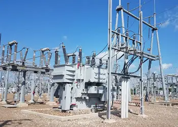
In parallel, best practices in electrical substation design emphasize equipment layouts that minimize vibration coupling paths across structures.
It is very often that “just putting some rubber” to isolate structures creates an inefficient or even a vibration isolation problem, without taking into account the characteristics of the whole system: such as media environment and temperature, material stiffness adjusted to the application load, surface area, material transmissibility, as well as pad design techniques, like shape factor conformity. These are fundamental to a good anti-vibration material selection and consequent noise reduction.Through experience in T&D applications, Amorim Cork Composites has implemented a priority 4 step system approach in analysis and treatment of “noisy” equipment. Our 4 step approach focuses on the need to control vibration before it reaches the tank structure (and therefore closer to the source of vibration), impeding that structural vibrations on the tank are transformed into airborne noise through the amplitude vibration of the tank walls acting as “speakers”. Typical noise reduction gains (cumulative gains) can also be observed when designing with ACC methodology (values based on project statistics). For example, high-speed vacuum circuit breakers can introduce impulsive excitation that makes proper material selection critical.
The Noise Conundrum
As T&D equipment become larger and more powerful, due to electrical grid complexity and natural energy sources, general tank construction relies on rigidity and stiffness to reduce the amplitude of vibrations that reach the tank wall, which are then released as airborne noise.
Whilst the increase of stiffness of the tank is achieved through the use of U-beams and profiles, this also increases the actual natural frequency (fn ) of the tank structure closing in on the gap between the disturbing frequency coming from the active part. The closeness of these two frequencies lead to an amplification in transmissibility and consequent increase in noise.
Though optimal mechanical construction is imperative for the functional characteristics of the equipment, noise level restrictions are already today part of the Utilities requirements due to end consumer demand. Switching sequences in substation breakers may align with structural modes if not accounted for during design reviews.
Natural Frequency
All anti-vibration pads/materials, components and systems have a natural frequency (fn). In case of the anti-vibration pad the natural frequency, fn, is dependent upon the stiffness of the pad material, K, and the mass of the load that it is supporting (M). In elastomeric materials the fn is not only defined by the actual material but also by its thickness and shape (see shape factor). ACC has defined the natural frequency in various thicknesses under dynamic conditions for its materials.
Download our FREE Electrical Training Catalog and explore a full range of expert-led electrical training courses.

Instrumentation such as capacitor voltage transformers can assist in correlating electrical disturbance frequencies with measured mechanical response.
Damping
Damping is the dissipation of energy, usually by releasing it in the form of low-grade heat. The loss factor quantifies the level of damping of a material, it is the ratio of energy dissipated from the system to the energy stored in the system for every cycle.
Due to corks closed cell structure filled with air, cork has a higher loss factor than rubber, essential to the damping function and consequent dissipation of energy. Our specific polymer formulations and the inclusion of cork, with unique compressibility and recovery characteristics, absorbs energy, yielding high material loss factors. Aligning materials selection with substation environmental design objectives helps meet community noise expectations.
Vibration Isolation
The performance of an isolation system is determined by the transmissibility of the system, the ratio of the Energy going into the system to the Energy coming out of the system. As a goal, vibration control design puts the disturbing frequency of the system in the isolation region The amount of damping in the isolation system will determine the height of peak transmissibility (fn) for the system. As damping increases, this peak value will decrease.
Amorim Vibration Control Materials exhibit significant material loss factors resulting in a lower amplification at resonance (fd=fn), giving them operational effectiveness over a broad range of frequencies.
Moreover, rigid bonding and grid connections defined by substation grounding practices can act as flanking paths unless isolation interfaces are specified.
Shape factor
Sf is the geometric measure for the shape of an anti-vibration pad, defined by the ratio of the loaded area and the area of the sum of the perimeter surfaces. The correct design of the shape fac-tor is important to achieve the cor-rect stiffness.
While rubbers are considered incompressible, needing space to dis-place the compressed volume, cork rubber displaces much less volume due to corks compression within itself (lower Poisson ratio), allowing for a wider Sf tolerance, which in turn affects the design robustness.
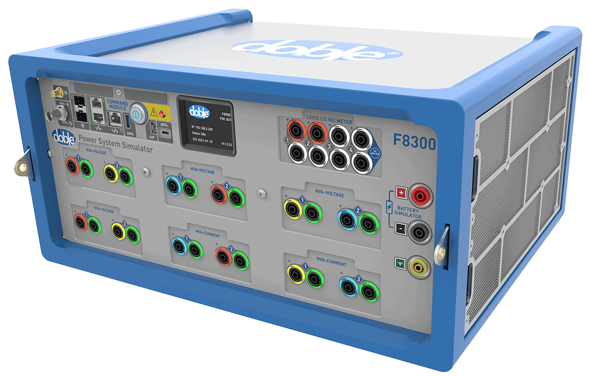
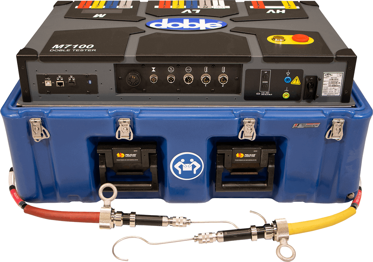
Doble Engineering Company is a global leader in diagnostic test equipment, software and engineering services for the electric power industry. Founded in 1920, it helps utilities and energy asset owners improve reliability, assess system health, and optimize operations through advanced diagnostics and expertise worldwide.
Contact us at sales@doble.com , or visit https://www.doble.com

Anti-vibration pad selection and design roadmap
While rubbers are considered incompressible, needing space to dis-place the compressed volume, cork rubber displaces much less volume due to corks compression within itself (lower Poisson ratio), allowing for a wider Sf tolerance, which in turn affects the design robustness.
NOTE: careful analysis of the system is crucial; extra-ordinary loadings should be taken in to account such as oil mass, loads introduced through anchoring or significant connections that may impact the overall seating stress on the anti-vibration pad. As rule of thumb when possible, design on the lower end of the material stress range to account for load variations and long term creep effects. Integrating condition data into RTU and HMI redundancy strategies supports continuous monitoring during commissioning and service.
Decoupling Active Part Design
Due to the fact that every manufacturer has a unique design and clamping requirements, that is then replicated through its product range, every design needs to be uniquely evaluated.
The importance of adequate decoupling at the clamping points, significantly enhances the effectiveness of the interior vibration pads, preventing flanking paths from the active part to the tank structure. Amorim VC2100 is used for the decoupling function.
Structural damping design
Structural damping provides a means of converting mechanical energy (vibrations) in to low-grade heat, if cor-rectly implemented it can significantly reduce noise.
Thickness of the CLD is defined by the tank wall, in an optimized design the CLD thickness should be similar to the tank wall thickness; too thin will have minimum or no effect at all, it should be implemented in the interior wall. Amorim VC2100 is the selected material for the CLD

NOTE: In equipment where a shunt wall is present, the actual shunt wall can serve as the compressing element of the CLD against the interior tank wall, this construction will also reduce the vibrations that are passed on by the shunt wall to the tank structure due to the loss currents from the active part.
Explore 50+ live, expert-led electrical training courses –