Electrical Distribution System
By Howard Williams, Associate Editor
By Howard Williams, Associate Editor
An electrical distribution system is the portion of the electric power grid that delivers electricity from distribution substations to end users through feeders, transformers, and service connections operating at medium and low voltage levels. It forms the physical link between transmission supply and electrical utilization by stepping voltage down and distributing it across local networks.
The system connects substations to loads through primary feeders and secondary circuits, which carry power from medium voltage networks to low voltage service points. This relationship defines how electrical energy moves from a bulk supply into a usable form without describing operational control or delivery processes.
An electrical distribution system establishes the structural framework of substations, feeders, transformers, and service connections that supply residential, commercial, and industrial loads. It defines system arrangement and voltage transition rather than how electricity is managed or restored.
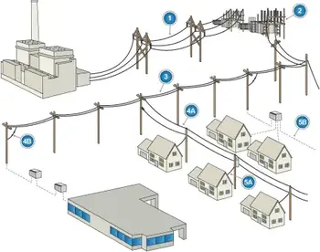
An electrical distribution system is built from interconnected elements that extend from the distribution substation to the point of use.
Distribution substations form the starting point of the system. They reduce transmission voltage to medium voltage levels suitable for distribution networks.
Feeders carry medium voltage electricity outward from the substation into service areas. These circuits supply multiple downstream loads and define the distribution network's reach.
Distribution transformers convert medium voltage to low voltage for utilization. They are installed along feeders to serve localized demand.
Service connections provide the final link between the distribution system and the customer, delivering electricity at usable voltage levels.
Together, these components define the physical structure of the system.

Electrical distribution systems are arranged using several standard configurations that determine how loads are connected.
Radial systems supply power through a single path from the substation to the load, with no alternate supply route.
Loop systems provide two possible paths to a load, although one path is typically open during normal conditions.
Network systems use multiple interconnected feeders and transformers to supply the same load area through several available paths.
These configurations describe structural arrangement rather than operational behavior.
Electrical distribution systems operate across defined voltage ranges that separate transmission supply from utilization.
The transition occurs at the distribution substation, where high voltage is reduced to medium voltage levels.
Medium voltage distribution typically ranges from about 4 kV to 35 kV and is used for primary feeder circuits.
Low voltage distribution is typically below 1 kV and supplies electricity directly to end-use equipment.
These voltage levels define how electrical energy is stepped down and delivered within the system.
An electrical distribution system serves as the interface between transmission infrastructure and electrical demand.
Its role is to provide the structure required to step down voltage and distribute electricity across service areas so it can be used by connected loads.
This function is defined by the arrangement of substations, feeders, transformers, and service connections rather than by operational processes.
An electrical distribution system is defined by its structure, components, and voltage levels.
It does not describe how electricity is delivered step by step, how outages are managed, or how systems are controlled. Those functions belong to separate process-focused and operational topics.
For process-focused coverage of electricity delivery, see
Electric Power Distribution
For component-level detail within the system, see
Electrical Distribution Equipment
Think you know Overhead T&D? Take our quick, interactive quiz and test your knowledge in minutes.
Explore 50+ live, expert-led electrical training courses –