Transformer Coil
By R.W. Hurst, Editor
Substation Maintenance Training
Our customized live online or in‑person group training can be delivered to your staff at your location.
- Live Online
- 12 hours Instructor-led
- Group Training Available
Download Our OSHA 3875 Fact Sheet – Electrical PPE for Power Industry Workers
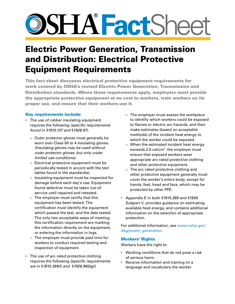
- Follow rules for rubber gloves, arc-rated PPE, and inspection procedures
- Learn employer obligations for testing, certification, and training
- Protect workers from arc flash and electrical shock injuries
A transformer coil is a conductive winding that transfers energy through electromagnetic induction. It regulates voltage between primary and secondary windings for efficient power conversion, electrical isolation, and current control across power distribution systems.
What is a Transformer Coil?
A transformer coil is a fundamental component in electrical devices that facilitates the transfer of electrical energy through electromagnetic induction.
✅ Converts voltage levels between primary and secondary windings
✅ Provides electrical isolation and magnetic coupling
✅ Enables efficient energy transfer in AC systems
A transformer coil is a fundamental component of electrical transformers, responsible for transferring electrical energy between circuits through the principle of electromagnetic induction. It enables voltage conversion, electrical isolation, and efficient power transmission across residential, industrial, and utility applications. The construction, materials, insulation, and winding arrangement of the coil determine how effectively a transformer performs its vital role in modern power systems. In large power transformers, the transformer coil must handle high current densities and heat dissipation challenges to maintain efficiency and voltage stability.
Electrical Transformer Maintenance Training
Substation Maintenance Training
Request a Free Training Quotation
Principle of Operation
The operation of a transformer coil is based on Faraday’s Law of Electromagnetic Induction, which states that a changing magnetic field induces an electromotive force (EMF) in a nearby conductor. A transformer typically contains two windings—the primary coil and the secondary coil—wound around a laminated magnetic core made of steel or iron. When alternating current (AC) flows through the primary coil, it generates a fluctuating magnetic flux in the core. This varying magnetic field links to the secondary coil, inducing a voltage across its terminals. Proper insulation around a transformer core and coil helps reduce eddy current losses, ensuring reliable magnetic flux linkage and long-term operational safety.
Electricity Today T&D Magazine Subscribe for FREE

- Timely insights from industry experts
- Practical solutions T&D engineers
- Free access to every issue
The relationship between the input and output voltages is governed by the turns ratio formula:
Vs = Vp * (Ns/Np)
where:
Vp = primary voltage
Vs = secondary voltage
Np = number of primary turns
Ns = number of secondary turns
For example, if the primary has 1,000 turns and receives 120 volts, and the secondary has 100 turns, the secondary voltage will be 12 volts. This simple relationship demonstrates how a step-down transformer reduces voltage while proportionally increasing current, and a step-up transformer does the opposite.
Primary and Secondary Coils
The primary coil is connected to the input power source and is responsible for producing the magnetic flux in the core. The secondary coil receives this magnetic energy and delivers an induced voltage to the load. Depending on the ratio of turns between the two windings, the transformer either raises or lowers voltage levels. The efficiency of this process depends on the tightness of the magnetic coupling between coils. In real transformers, losses occur due to leakage flux, winding resistance, and core effects such as hysteresis and eddy currents, all of which slightly reduce performance compared to the ideal model. Modern distribution transformers use advanced winding configurations that improve the performance and durability of the transformer coil in medium-voltage networks.
Influence of Coil Turns and Trade-Offs
The number of turns in the primary and secondary windings directly affects the voltage transformation ratio. A greater number of turns in the secondary increases the induced voltage, while fewer turns reduce it. However, increasing the number of turns also increases resistance and copper loss, leading to heat buildup and energy inefficiency. Transformer designers therefore balance electrical efficiency, thermal management, and magnetic coupling to achieve the optimal configuration for each application. Precision manufacturing and testing play a vital role in coil performance, especially in substation transformers where mechanical vibration and thermal expansion can affect winding integrity.
Winding Configurations
Transformer coils can be wound in several configurations, each offering distinct performance characteristics.
-
Concentric Windings: Cylindrical coils wound one over the other, with the low-voltage winding typically placed nearest the core for improved cooling and magnetic coupling.
-
Interleaved Windings: Alternating sections of primary and secondary windings that reduce leakage flux and improve coupling but may increase capacitance at high frequency.
-
Helical Windings: Conductors wound helically around the core, providing excellent mechanical strength and cooling for high-current applications.
-
Disc Windings: Multiple disc-shaped sections that evenly distribute voltage stress and resist mechanical deformation in high-voltage devices.
-
Sandwich (Layered) Windings: Alternating layers of primary and secondary windings that minimize leakage inductance and are common in compact or medium-power transformers.
Each design involves trade-offs between coupling efficiency, heat dissipation, mechanical strength, and dielectric performance. The quality and condition of a transformer’s insulation system are crucial to preventing dielectric failure between coils under high-voltage stress.
Materials and Insulation
Copper is the preferred conductor for most transformer coils due to its high electrical conductivity, mechanical durability, and resistance to fatigue. Aluminum is sometimes used in larger power transformers where cost and weight reduction are priorities.
Proper insulation is vital for safety and performance. Common materials include enamel coatings, paper, and polyester film, each chosen for its dielectric strength and thermal rating. For high-voltage coils, additional insulation such as varnish or resin impregnation enhances heat conduction and mechanical stability. Understanding the construction of a transformer helps engineers design coils with optimal turns ratios, minimizing leakage flux and improving magnetic coupling efficiency.
| Insulation Material | Dielectric Strength (kV/mm) | Temperature Rating | Typical Use |
|---|---|---|---|
| Enamel Coating | 3–4 | 105–155°C | Small coils and low voltage |
| Paper Insulation | 6–10 | 90–120°C | Layer insulation |
| Polyester Film | 6–8 | 130–180°C | High-density coils |
| Varnish or Resin Impregnation | 10–15 | 180°C+ | High-voltage, moisture-resistant coils |
International standards such as IEEE C57 and IEC 60076 define insulation coordination, dielectric testing, creepage distances, and acceptable limits for voltage stress. These guidelines help ensure safety and reliability across transformer designs.
Sign Up for Electricity Forum’s Utility Transformers Newsletter
Stay informed with our FREE Utility Transformers Newsletter — get the latest news, breakthrough technologies, and expert insights, delivered straight to your inbox.
Real vs. Ideal Performance
An ideal transformer would transfer energy perfectly, with no losses. In practice, efficiency is slightly reduced by several physical factors:
-
Copper loss: Resistance in the windings produces heat and energy loss.
-
Core loss: Hysteresis and eddy currents in the core material dissipate energy.
-
Leakage flux: Not all magnetic lines link the two windings completely.
-
Mechanical vibration and hum: Caused by magnetostriction in the core material.
Engineers minimize these inefficiencies by using high-quality materials, optimized winding geometry, and grain-oriented steel cores that improve magnetic flux linkage.
Manufacturing and Quality Control
Transformer coil manufacturing demands precision. Wire tension, winding alignment, and spacing tolerances are tightly controlled to ensure consistent performance. Modern production facilities use machine-vision inspection to detect insulation flaws, spacing errors, or layer misalignments. Coils undergo dielectric testing, thermal cycling, and resistance measurement to confirm mechanical and electrical integrity. Standards from IEEE and IEC specify quality benchmarks for insulation endurance, creepage distance, and dielectric strength. These procedures ensure that transformer coils can withstand the mechanical stress and thermal expansion inherent in high-power operation.
Applications of Transformer Coils
Transformer coils are found in nearly every segment of the electrical industry. They are central to power distribution transformers in substations, which step voltages up or down for efficient transmission. In isolation transformers, electrical separation between circuits is provided to enhance safety and reduce noise. Audio transformers improve signal integrity and impedance matching in sound equipment, while switch-mode power supply (SMPS) transformers employ ferrite cores and high-frequency windings for compact, efficient conversion in electronics.
Advanced designs such as planar transformers, used in high-frequency converters and renewable energy systems, exemplify ongoing innovation in transformer coil design. Research by institutions such as the National Renewable Energy Laboratory (NREL) demonstrates the potential of planar windings to reduce losses and improve energy density.
A practical example is a 100 kVA distribution transformer using 500 turns of 10 mm² copper for the primary winding and 250 turns for the secondary, achieving approximately 98.5% efficiency. Optimized winding geometry, precise insulation, and effective cooling all contribute to this high level of performance.
Common Issues and Preventive Measures
Transformer coils are subject to operational stresses that can affect longevity. The familiar hum of a transformer is caused by magnetostriction, the physical expansion and contraction of the core under alternating magnetic fields. Proper clamping, insulation varnish, and mechanical bracing reduce vibration and noise.
Degraded insulation can lead to partial discharge or arcing, which, over time, causes overheating and failure. Regular testing, including insulation resistance and hipot testing, helps identify early signs of degradation. Leakage inductance, another common issue, can be minimized by interleaving windings and reducing physical separation between coils.
Transformer coils are the essential link in the transfer of electrical energy between circuits. Their design integrates science, engineering, and precision manufacturing to ensure safety, reliability, and efficiency. Every detail—from the number of turns and choice of materials to insulation and quality control—determines how effectively a transformer performs its role. Whether used in household electronics or high-voltage substations, transformer coils embody the principles of electromagnetic induction that power the modern world.
Related Articles


