Transformer Insulation Explained
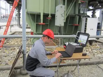
Substation Maintenance Training
Our customized live online or in‑person group training can be delivered to your staff at your location.
- Live Online
- 12 hours Instructor-led
- Group Training Available
Download Our NFPA 70E Fact Sheet – 2024 Electrical Safety Edition
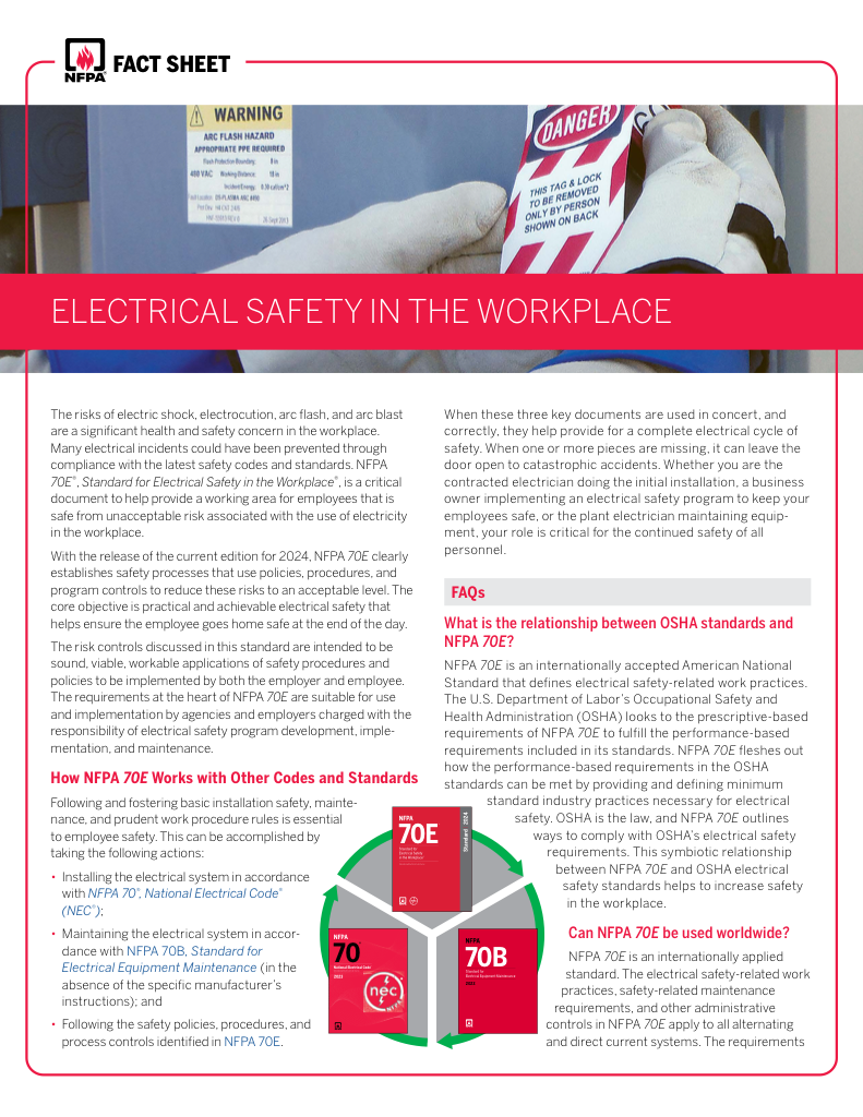
- Understand how NFPA 70E works with NEC and NFPA 70B standards
- Clarify the shared responsibility between employers and employees
- Learn how NFPA 70E supports OSHA compliance
Transformer insulation ensures dielectric strength and thermal endurance using cellulose paper, pressboard, varnish, and fluids like mineral oil or synthetic esters, mitigating moisture, aging, and partial discharge for reliable power transformers per IEC/IEEE standards.
What Is Transformer Insulation?
Transformer insulation is the dielectric system that controls heat, moisture, and electrical stress to prevent failures.
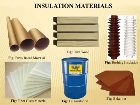
✅ Materials: cellulose paper, pressboard, epoxy, NOMEX, varnish
✅ Fluids: mineral oil, natural/synthetic esters, silicone liquids
✅ Performance: dielectric strength, thermal class, moisture control
Transformer Insulation
Insulation systems in power transformers consist of a fluid—either liquid or gas—together with solid materials. Petroleum-based oils have been used to insulate power transformers since 1886 and the mid-1970s when the flammability of mineral oil was a concern, but it has since been completely phased out of transformer production because of environmental concerns. It has been replaced by any of a wide variety of high-flash-point fluids (silicones, high-flash-point hydrocarbons, clorinated benzenes, or chlorofluorocarbons). Gas systems include nitrogen, air, and fluorogases. The fluorogases are used to avoid combustabiity and limit secondary effects of internal failure. Some transformers have been constructed using low boiling-point liquids such as Freon which allows improved heat transfer using a 2-phase cooling system.
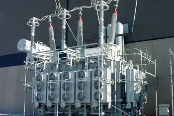
A practical understanding of the tank, bushings, windings, cooling circuits, and insulating media is aided by this overview of transformer components used across utility applications.
Oil-Insulated Transformers
Low cost, high dielectric strength, excellent heat transfer characteristics, and ability to recover after dielectric overstress make mineral oil the most widely used transformer insulating material. The oil is reinforced with solid insulation in various ways. The major insulation usually includes barriers of wood-based paperboard (pressboard), the barriers usually alternating with oil spaces. Because the dielectric constant of the oil is 2.2 and that of the solid is approximately 4.0, the dielectric stress in the oil ends up being higher than that of the pressboard, and the design of the structure is usually limited by the stress in the oil. For context, the chemistry, testing regimes, and dielectric characteristics of modern transformer oil inform both material selection and service procedures.
FREE EF Electrical Training Catalog
Download our FREE Electrical Training Catalog and explore a full range of expert-led electrical training courses.

- Live online and in-person courses available
- Real-time instruction with Q&A from industry experts
- Flexible scheduling for your convenience
The insulation on the conductors of the winding may be enamel or wrapped paper which is either wood- or nylon-based. The use of insulation directly on the conductor actually inhibits the formation of potentially harmful streamers in the oil, thereby increasing the strength of the structure. Again, the limit of dielectric strength is usually that of the oil.
These material choices directly influence thermal performance and moisture control in an oil-filled transformer during both normal loading and through-fault events.
Heavy paper wrapping is also usually used on the leads coming from the winding. In this case, the insulation serves to reduce the stress in the oil by moving the interface from the surface of the conductor (where the stress is high) to a distance away from the conductor (where the stress is considerably lower). Again, the stress in the oil determines the amount of paper required, and the thermal considerations establish the minimum size of the conductor for the necessary insulation. Operators often verify these clearances and condition indicators through inspection windows during routine maintenance rounds.
Askeral-Insulated Transformers
These transformers have constructions similar to the oil-insulated transformers. The relatively high dielectric constant of the askeral aids in transferring the dielectric stress to the solid elements. Askeral has limited ability to recover after dielectric overstress, and thus the strength is limited in nonuniform dielectric fields. Askerals are seldom used over 34.5-kV operating voltage. They are powerful solvents; their products of decomposition are so harmful that they have been completely abandoned in transformers manufactured after the mid-1970s. Consequently, modern high-voltage transformers rely on alternative dielectrics and engineered solids to meet stringent environmental and performance criteria.
Fluorogas-Insulated Transformers
Fluorogases have better dielectric strength than nitrogen or air-Although their heat transfer characteristics are poorer than oil, they are better than nitrogen or air because of their higher density. Both dielectric strength and heat transfer capability increase with pressure; in fact, the dielectric strength at 3 atm gage pressure—where some fluorocarbon-insulated transformers operate—can approach that of oil. The gas insulation is reinforced with solid insulation used in the form of barriers, layer or disk insulation, turn insulation, and lead insulation similar to oil-immersed transformers.
It is usually economical to operate fluorogas-insulated transformers at higher temperatures than oil-insulated transformers. Suitable solid insulating materials include glass, asbestos, mica, high-temperature resins, and ceramics.
Dielectric stress on the gas is several times higher than in the adjacent solid insulation; care mUst be taken to avoid overstressing the gas.
Nitrogen and Air-Insulated Transformers
These are generally limited to 34.5 kV and lower operating voltages. Air-insulated transformers in clean locations are frequently ventilated to the atmosphere. In contaminated atmospheres a sealed construction is required, and nitrogen is generally used at approximately 1 atm and some elevated operating temperatures.
Design of Insulation Structures
Three factors must be considered in the evaluation of the dielectric capability of an insulation structure—the voltage distribution must be calculated between different parts of the winding, the dielectric stresses are then calculated knowing the voltages and the geometry, and finally the actual stresses can be compared with breakdown or design stresses to determine the design margin. These assessments are foundational to disciplined transformer design practices that balance dielectric strength, thermal limits, and mechanical robustness.
Electricity Today T&D Magazine Subscribe for FREE

- Timely insights from industry experts
- Practical solutions T&D engineers
- Free access to every issue
Voltage distributions are linear when the flux in the core is established. This occurs during all power frequency test and operating conditions and to a great extent under switching impulse conditions. (Switching impulse waves have front times in the order of tens to hundreds of microseconds and tails in excess of 1000 ps.) These conditions tend to stress the major insulation and not inside of the winding. For shorter-duration impulses, such as full-wave, chopped-wave, or front-wave, the voltage does not divide linearly within the winding and must be determined by calculation or low-voltage measurement. The initial distribution is determined by the capacitative network of the winding. For disk and helical windings, the capacitance to ground is usually much greater than the series capacitance through the winding. Under impulse conditions, most of the capacitive current flows through the capacitance to ground near the end of the winding, creating a large voltage drop across the line end portion of the coil.
The capacitance network for shell form and layer-wound core form results in a more uniform initial distribution because they use electrostatic shields on both terminals of the coil to increase the ratio between the series and to ground capacitances. Static shields are commonly used in disk windings to prevent excessive concentrations of voltages on the line-end turns by increasing the effective series capacitance within the coil, especially in the line end sections. Interleaving turns and introducing floating metal shields are two other techniques that are commonly used to increase the series capacitance of the coil.
Selecting shield geometry, spacing, and interleaving patterns within the transformer coil helps tune series and ground capacitances for controlled impulse distribution.
Following the initial period, electrical oscillations occur within the windings. These oscillations impose greater stresses from the middle parts of the windings to ground for long-duration waves than for short-duration waves. Very fast impulses, such as steep chopped waves, impose the greatest stresses between turns and coil portions. Note that switching impulse transient voltages are two typesasperiodic and oscfflatory. Unlike the asperiodic waves discussed earlier, the oscillatory waves can excite winding natural frequencies and produce stresses of concern in the internal winding insulation.


