Control Switches for Arc Flash and Blast Protection
It may seem like a long time ago, but with respect to the age of the earth, electricity is in its infancy. When such famous names as Franklin, Edison, Tesla, and Volta were mesmerized by that “blue flame”, who could have imagined the unlimited potential (no pun intended). Electricity is part of everyone’s life and living without it is practically impossible.
The biggest task after the discovery of electricity was developing a way to generate and harness such a wild beast. Today, we walk into a room, turn on a light, appliance, fan, or any number of devices but never really think about exactly how the power got to its destination.
Since usable electricity does not exist naturally, it must be generated. Almost all commercial electricity is produced using a turbine driven by wind, water, or steam to rotate a magnet inside a coil of wire commonly referred to as a generator. A group of generators or power plant can then be used to send electricity via transmission lines at very high voltages to power substations where transformers reduce the voltages down to voltage that is suitable for consumer use and distribution.
Once the power is in a usable state, it is connected to a series of fuses and circuit breakers commonly referred to as switchgear. Switchgear is used to control, protect and isolate electrical equipment in addition to de-energize the equipment for maintenance or to clear faults downstream from a breaker.
During the turning “ON” of circuit breakers either for new installations or after equipment maintenance or repair, there exists the possibility of significant fault currents due to wiring errors or conductors being in too close proximity of each other or ground. This is a condition known as “arc flash and blast”. Arc flash is the immediate light produced with the fault. Arc blast is the release of energy from the fault that can be strong enough to throw personnel to the ground and cause equipment damage. Arc blasts can also result in hearing loss and can cause loose equipment, tools and debris to become deadly projectiles.
Industrial Safety and Hygiene News estimated that, on average, there are 30,000 arc flash incidents every year resulting in an average annual totals of 7,000 burn injuries, 2,000 hospitalizations, and 400 fatalities. OSHA mandates that employers identify electrical hazards, warn employees about the hazards and provide them proper protection and training regarding the hazards. Understanding arc flash compliance is often complicated. While OSHA tells you “what to do” for arc flash, they don’t tell you “how” to do it.
So exactly how do you close or open an industrial circuit breaker?
Typically, a circuit breaker is a mechanism driven by the mechanical energy stored in springs. The closing spring is mechanically charged by a motor and is held in its compressed position by a closing latch. When a close signal releases this latch, this spring pushes against a mechanical linkage to force the breaker contacts closed and, at once, charges the trip spring. The closing spring is then immediately recharged by the motor. Another latch will hold the tripping spring in the compressed position until an open signal releases this latch.
In order to get the signal to the tripping and closing latches, a device known as a Control Switch is incorporated in the switchgear. Control switches are configured in an infinite number of ways depending on the design of the switchgear and the number of functions required in addition to the “Trip” and “Close” task.
Shallco, Inc. started the manufacturing of Industrial Control Switches and Protective Lock-out relays more than 20 years ago. Shallco offers standard Breaker Control Switches, Selector Switches, Ammeter, and Voltmeters Switches along with thousands of customer specified switches to perform any switching task engineers might require.
Remote operation: In order to perform distant operation of the control switch, a rotary and linear solenoid drive mechanism was integrated into the standard manually operated switch. The result - two types of operation in one package. A standard manual shaft rotation and/or a remote electrical operation.
Now, what is needed to protect the operator from the arc fault and blast described previously?
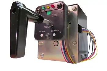
Answer: Shallco added a microprocessor controlled signaling board and a LED indicating operation panel that allows the operator from 10 seconds up to 2 minutes to vacate the danger zones. The operation is pretty straight forward. There are two operating buttons on the front of the lighted panel.
DELAY TRIP OPERATION
Pressing and holding the delay/trip button for 4 seconds or greater will initiate the delay trip operation. The left (green) led will start flashing and will remain flashing after the button is released. After a few additional seconds, the led will begin to flash faster. After 10 seconds (up to 2 minutes depending on the programing), the breaker will trip
To cancel the operation, press either the delay/trip or delay close button at any time after the operation is initiated.
DELAY CLOSE OPERATION
Pressing and holding the delay/close button for 4 seconds or greater will initiate the delay close operation. The right (red) led will start flashing and will remain flashing after the button is released. After a few additional seconds, the led will begin to flash faster. After 10 seconds (up to 2 minutes depending on the programing), the breaker will close.
To cancel the operation, press either the delay/trip or delay close button.
The relay also provides connections for user selectable 52A or 52B contacts. These are part of an independent circuit connection to the LED’s on the front panel and can be used to indicate any condition the user might need.
"Shallco added a microprocessor controlled signaling board and a LED indicating operation panel that allows the operator from 10 seconds up to 2 minutes to vacate the danger zones."
The center LED is commonly used as Trip Coil Monitor Circuit with a SCADA output.
All knobs, terminal screws, knobs and mounting screws are provided and custom front panel engraving is available.
Since the control center of operation for the Shallco Control Switch Relay is a microprocessor, the number of possibilities for future additions or advancements is endless.
Shallco Series 26 Control Switches are manufactured in the United States using the highest quality materials and are UL and cUL recognized. Shallco has been in operation for more than 50 years has been an ISO-9001 company since 2003
If you would like more information about Shallco Control Switches, Control Switch Relays, Lockout Relays or any of the hundreds of Shallco Industrial Control Products, please visit our website at www.shallco.com. There are also videos available on YouTube.
Additionally, experienced professionals are available and can be reached via the website “contact” section (https://shallco.com/contact/) email (shallco@shallco.com) or phone 800-876-3135.
EF PARTNER MEDIA
Videos
Product Showcases
Shared Media


