Current Transformer Simulation
Substation Maintenance Training
Our customized live online or in‑person group training can be delivered to your staff at your location.
- Live Online
- 12 hours Instructor-led
- Group Training Available
Download Our OSHA FS3529 Fact Sheet – Lockout/Tagout Safety Procedures
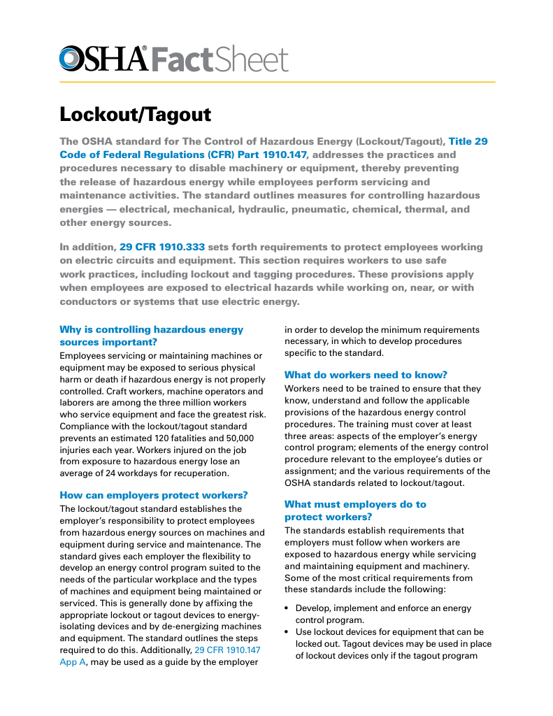
- Learn how to disable machines and isolate energy sources safely
- Follow OSHA guidelines for developing energy control programs
- Protect workers with proper lockout devices and annual inspections
Current transformer simulation models how CTs behave under electrical load, helping engineers test system performance, accuracy, and safety. It’s vital for power system design, fault analysis, and protective relay coordination.
What is Current Transformer Simulation?
Current transformer simulation is the virtual modelling of CT behaviour in electrical systems.
✅ Accurately predicts CT performance under various load and fault conditions
✅ Helps design, test, and validate protective relay systems
✅ Enhances power system safety, measurement, and fault analysis
Current transformer simulation is critical for industrial electricians, as it allows for accurate analysis and troubleshooting of electrical systems without disrupting operations. Understanding how to simulate devices ensures system reliability, optimizes power distribution, and upholds safety standards in complex industrial environments. This article explores the principles of simulation, its practical applications, and best practices for using simulation tools effectively—empowering you to tackle electrical challenges with confidence. Understanding the function of a transformer is fundamental before diving into how CT simulations model electrical behavior in complex power systems.
Electrical Transformer Maintenance Training
Substation Maintenance Training
Request a Free Training Quotation
The Role of Simulation Software and Tools
Accurate current transformer simulation has become essential for engineers and designers working with power systems. These simulations provide valuable insights into how CTs operate under different conditions, helping optimize their performance and ensure real-world reliability. By combining advanced software tools with precise modeling techniques, engineers can predict device behavior more accurately. In real-world applications, especially in substations, electrical substation transformers play a critical role, and simulating their CTs helps ensure fault detection and relay protection accuracy.
For example, when simulating a high-voltage transformer in a power plant, engineers can anticipate how it will respond during peak load hours and adjust parameters to prevent unexpected failures. This proactive approach saves time, prevents downtime, and enhances system reliability.
FREE EF Electrical Training Catalog
Download our FREE Electrical Training Catalog and explore a full range of expert-led electrical training courses.

- Live online and in-person courses available
- Real-time instruction with Q&A from industry experts
- Flexible scheduling for your convenience
Current Transformer Simulation – Comparison Table
| Feature | Real CT Testing | Software-Based Simulation | Hardware-in-the-Loop (HIL) Simulation |
|---|---|---|---|
| Purpose | Validates physical CT performance | Models CT behavior in virtual systems | Combines real-time CT data with digital simulation |
| Accuracy | High (actual measurements) | High, but depends on model fidelity | Very high with real-time data feedback |
| Cost | Expensive (equipment, setup) | Low to moderate | High (specialized equipment required) |
| Safety | Involves high-voltage risks | Completely safe | Safe but requires interface isolation |
| Flexibility | Limited to available CT types | Highly flexible (any rating or class) | Flexible, but constrained by hardware interfaces |
| Time Efficiency | Time-consuming setup and testing | Fast simulations with repeatable conditions | Moderate, real-time capable but setup-intensive |
| Use in Relay Coordination | Manual testing with actual CTs | Simulates relay response accurately | Real-time dynamic testing with actual relays |
| System Fault Analysis | Limited to historical or lab conditions | Models various fault scenarios and load flows | Real-time fault injection and CT reaction monitoring |
| Training & Education | Less practical for classrooms | Ideal for training and learning environments | Suitable for advanced engineering education |
Understanding Core Saturation Effects
Core saturation is a crucial phenomenon in operation. When a CT’s magnetic core becomes saturated, its ability to transform current accurately diminishes, leading to distorted outputs and potentially compromising protective systems. This issue is especially common during fault conditions or high-load scenarios.
To illustrate, imagine a manufacturing plant experiencing a short circuit. If the CT’s core becomes saturated, the protective relays may receive incorrect readings, delaying their response. Simulating core saturation allows engineers to predict these issues and design CTs that can withstand extreme conditions. CT simulations are especially valuable when working with high-voltage transformers, where performance under stress must be precisely analyzed without risking actual equipment.
Ensuring Accuracy Through Error Analysis
Another critical aspect of CT simulation is ensuring accuracy. Discrepancies between simulation results and real-world performance can lead to inefficiencies or even failures in applications where precision is non-negotiable.
Error analysis plays a key role here. By comparing simulated data with experimental results, engineers can identify potential sources of error, such as inaccurate material properties or overlooked nonlinearities. This process improves modeling techniques and ensures that simulations remain a reliable tool for guiding system design. Engineers designing CTs also benefit from understanding key physical components, like the transformer core, since core properties directly affect saturation and modeling accuracy.
Practical Applications and Troubleshooting
Current transformer simulation goes beyond design—it plays a vital role in troubleshooting and system optimization. For instance, in renewable energy systems, CT simulations help fine-tune the integration of solar and wind energy into existing grids. In industrial facilities, simulations can diagnose issues like insulation breakdown, overvoltage conditions, and overheating before they escalate into costly problems.
One real-world example involves identifying thermal inefficiencies in an industrial substation. By simulating different load conditions, engineers can pinpoint areas where excessive heat builds up and adjust the system to improve cooling and prevent equipment failure. For effective CT testing in the field, condition data from maintenance inspection windows on transformers can validate simulation results and improve long-term reliability.
Beyond the Design Phase
The benefits of simulation extend well beyond initial design. In metering applications, simulations help ensure that CTs provide precise readings, even when load conditions fluctuate throughout the day. In protective systems, accurate simulations prevent malfunctions by ensuring relays receive correct input signals, minimizing false trips or failures to respond during emergencies.
This versatility demonstrates how simulation supports both innovation and day-to-day operational excellence, making it an indispensable tool in modern electrical engineering.
Frequently Asked Questions
How can I simulate a CT in MATLAB or Simulink?
To simulate a CT in MATLAB or Simulink, you need to model its core and windings accurately. Use coupled inductors or mutual inductance blocks to represent the primary and secondary windings, specifying parameters such as the turns ratio and impedance. Magnetic core properties—such as permeability, cross-sectional area, and core length—should also be defined. Include nonlinear effects like core saturation and hysteresis using lookup tables or built-in Simscape components. Don’t forget to model the secondary load impedance, as this affects the CT’s performance.
What parameters are critical for accurate current transformer simulation?
Critical parameters include the turns ratio, core permeability, core area, and saturation flux density. Other key factors are winding resistance, leakage inductance, and the coupling coefficient. The burden (load impedance) connected to the secondary side must be accounted for, as it influences accuracy. Additionally, consider the CT’s frequency response and excitation current, which accounts for core losses.
Electricity Today T&D Magazine Subscribe for FREE

- Timely insights from industry experts
- Practical solutions T&D engineers
- Free access to every issue
How does core saturation affect a CT?
Core saturation occurs when the magnetic core reaches its flux density limit, causing nonlinear behavior. This results in distorted outputs and can impact protective systems. Simulations capture this effect using the B-H curve, which relates magnetic flux to field intensity. You can use Simscape blocks or custom MATLAB equations to represent these nonlinearities.
What are the common challenges in CT simulation?
Common challenges include failing to account for nonlinearities such as saturation and hysteresis, using incorrect parameter estimates, and misrepresenting the secondary burden impedance. Numerical instabilities can also arise from poor solver configurations or time step sizes. Additionally, neglecting frequency-dependent effects like eddy currents can compromise the accuracy of the simulation.
How do I validate a CT simulation against real-world data?
To validate a simulation, compare its results with manufacturer-provided specifications for ratio error, phase angle error, and saturation characteristics. Laboratory tests using controlled sinusoidal and transient inputs can also confirm accuracy. Comparing the transient response during fault scenarios helps ensure the model aligns with real-world behavior. Field measurements from actual installations serve as a practical benchmark for confirming simulation fidelity.
Current transformer simulation is a multidimensional process that combines advanced software, meticulous modeling, and real-world validation. By leveraging these tools, engineers can design CTs that exceed performance expectations and contribute to the efficiency and stability of modern power systems. As simulation technologies evolve, the potential for innovation in CT design and application will only grow, paving the way for more reliable and sustainable energy solutions.
Related Articles


