Apparent Power vs Real Power
By John Houdek, Power Quality Editor
By John Houdek, Power Quality Editor
Our customized live online or in‑person group training can be delivered to your staff at your location.

Apparent power vs real power explains the difference between total electrical demand and the power that actually performs work in an AC circuit. Understanding this relationship helps improve efficiency, power factor, and system design.
In alternating-current systems, not all power drawn from the source is converted into useful output. Some of it does real work, such as turning a motor shaft or producing light. Some of it supports the operation of magnetic and electric fields inside equipment. Both forms matter, but they serve very different purposes. A deeper explanation of apparent power (S) is provided in our Apparent Power article, which covers its role in AC circuits.
Apparent power represents the total electrical demand placed on the system. It is measured in volt-amperes and reflects the combined effect of usable power and reactive power flowing through the circuit. Real power, measured in watts, is the portion that actually delivers energy to the load and gets converted into motion, heat, or light.
Power Quality Analysis Training
Request a Free Power Quality Training Quotation
The difference between the two becomes noticeable in systems that use motors, transformers, or other inductive or capacitive loads. These devices require reactive power to operate, which increases the total current even though they do not produce additional useful output. As a result, conductors, transformers, and generators must be sized for apparent power, not just real power.
Understanding this relationship is essential for system design, energy efficiency, and cost control. It explains why poor power factor leads to higher demand charges, increased losses, and unnecessary strain on the electrical infrastructure. Once the distinction between apparent and real power is clear, concepts like power factor correction and reactive compensation become much easier to understand. If you need practical calculations, our Apparent Power Calculator and Apparent Power Formula pages provide step-by-step methods.
Think you know Power Quality? Take our quick, interactive quiz and test your knowledge in minutes.
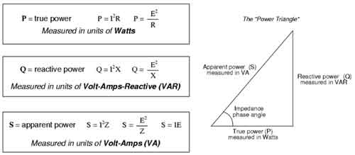
In AC systems, complex power (S) is expressed as the sum of real power (P) and reactive power (Q):
S = P + jQ
Real power (P) = V × I × cos φ, measured in watts (W or kW)
Reactive power (Q) = V × I × sin φ, measured in volt ampere reactive (VAR or kVAR)
Apparent power (S) = V × I, measured in volt-amperes (VA or kVA)
Here φ (phi) represents the phase angle between voltage and current. The cosine of φ (cos φ) is the PF, while sine of φ (sin φ) determines the reactive portion. This breakdown shows why systems with inductors or capacitors generate Q and why utilities must size equipment for S, not just P.
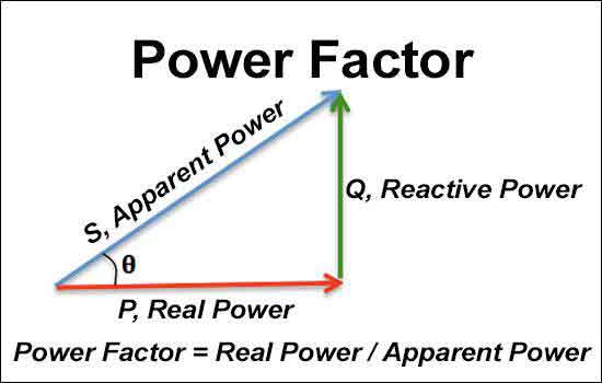
The power triangle illustrates the relationship between apparent, real, and Q.
The horizontal axis represents real power (P).
The vertical axis represents reactive power (Q).
The hypotenuse represents apparent power (S).
Mathematically: S² = P² + Q²
This visualization makes it clear that S is the vector sum of real and reactive components. It also helps in transformer and generator sizing, since equipment must handle S even though only P performs useful work.
Think of it like a beer mug: the beer you drink is P, the foam on top is Q, and the total glass volume is S. The foam doesn’t quench your thirst, but the mug still has to hold it.
| Aspect | Apparent Power (S) | Real Power (P) |
|---|---|---|
| Definition | Total energy supplied to an AC circuit, including real and reactive components | Usable energy consumed by the load to perform actual work |
| Unit of Measurement | Volt-Amperes (VA) | Watts (W) |
| Formula | S = V × I | P = V × I × PF |
| Role in System | Represents overall demand placed on the source | Represents the portion of energy converted into useful output |
| Efficiency Impact | Higher than P when Q is present, lowering efficiency | Indicates true efficiency of energy use |
| Examples | Includes both lighting and reactive effects of motors or transformers | Powers devices like lights, heaters, and motors doing useful work |
| Relation to PF | Always equal to or greater than P, depending on phase angle | Always less than or equal to S; increases when PF improves |
AP refers to the total electrical energy supplied, including both usable and unusable components. RP is the actual energy consumed by devices to perform useful work.
To better understand the overall context, see our Power Quality guide, which explains how apparent and P affect efficiency and system performance.
The presence of Q, caused by inductive or capacitive loads, creates a phase shift between current and voltage, increasing S without raising P. This is why utilities emphasize PF correction using devices like an Automatic Power Factor Controller, as it works in real applications.
Real power (P) = V × I × cos φ
Apparent power (S) = V × I
Reactive power (Q) = V × I × sin φ
In a purely resistive load, cos φ = 1, meaning real and S are equal.
They form the power triangle, with S² = P² + Q². The cosine of the phase angle (cos φ) is the PF, showing how efficiently a system converts apparent into P.
Improving this ratio (PF) means greater efficiency, smaller load sizing, lower energy bills, and reduced strain on the grid. Utilities may penalize low PF because infrastructure must be designed for S. Learn more in our How to Calculate Power Factor guide.
A lagging PF occurs in inductive loads (motors, transformers), while capacitive loads cause a leading PF. Both reduce efficiency, but correction methods differ.
Capacitors are rated in kVAR and chosen to offset the system’s reactive demand. By reducing Q, they bring S closer to P, improving overall performance.
In an AC system, understanding the relationship between apparent, real, and Q is vital for optimizing energy use. By calculating these values and improving the PF, facilities can enhance efficiency, lower costs, and ensure smoother, more reliable performance. For deeper insights, see how Power Factor Correction reduces reactive losses and strengthens the link between apparent and P.
Download our FREE Electrical Training Catalog and explore a full range of expert-led electrical training courses.

Advantages To Instructor-Led Training – Instructor-Led Course, Customized Training, Multiple Locations, Economical, CEU Credits, Course Discounts.
Request For QuotationWhether you would prefer Live Online or In-Person instruction, our electrical training courses can be tailored to meet your company's specific requirements and delivered to your employees in one location or at various locations.