Power Quality
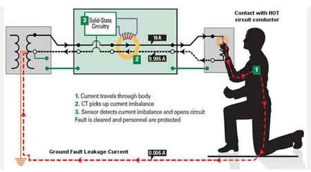
Electrical Ground Faults Explained
Download Our FREE Power Quality Handbook
Power Quality And Electrical Grounding Handbook Vol.6
This 100+ page handbook discusses all aspects of power quality management and electrical grounding issues with practical information on how to detect, treat and resolve costly power disturbances (transients and harmonics) and electrical grounding problems.
This volume is specifically designed for engineers, electrical professionals, and system designers who are involved in the design, implementation, and maintenance of electrical systems. It delves deeply into the causes and consequences of power quality disturbances, such as voltage sags, harmonics, and transients, and offers practical solutions to mitigate these issues. The book also provides a thorough understanding of grounding systems, addressing best practices for designing and installing safe, effective grounding solutions to protect both people and equipment from electrical faults.
With a balance of theory and practical guidance, Volume 6 focuses on the interrelationship between power quality and grounding, exploring how each component influences system performance and overall electrical safety. In addition to traditional methods, it introduces modern technologies, advanced diagnostic tools, and strategies for resolving common power quality issues and optimizing grounding systems.
Latest Power Quality Articles
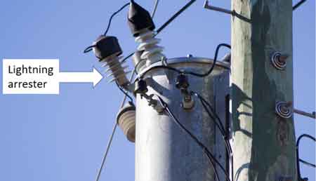
Lightning Arrester Explained
How to Find Power Factor
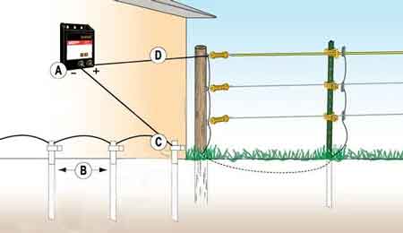
Electric Fence Ground Rod Requirements
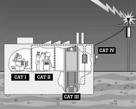
Power Quality Troubleshooting and Threshold Discipline
Electrical Ground Rod Installation Guide