Reactive Power Formula in AC Circuits
By R.W. Hurst, Editor
By R.W. Hurst, Editor
Our customized live online or in‑person group training can be delivered to your staff at your location.

Reactive power formula calculates the non-working electrical power in an AC circuit caused by phase difference between voltage and current. Engineers use it to evaluate power factor, transformer loading, voltage stability, and system capacity limits.
Reactive power represents the portion of electrical power that sustains electromagnetic fields in inductive and capacitive equipment. It does not perform useful work but is necessary for motors, transformers, and other AC devices to operate. Because this circulating energy still increases current flow, it affects conductor heating, voltage regulation, and overall system loading.
The reactive power formula expresses this relationship as:
Q = V × I × sin(φ)
where:
Q = reactive power in volt-amperes reactive (VAR)
V = RMS voltage in volts
I = RMS current in amperes
φ = phase angle between voltage and current
This equation defines the amount of electrical capacity consumed by field-sustaining energy rather than productive output. When reactive power increases, apparent loading rises even if real power remains unchanged. As a result, transformers, feeders, and switchgear may approach their thermal limits before real demand appears excessive.
In practical engineering work, reactive power must always be interpreted alongside apparent power and power factor. Reactive current calculations are inseparable from total Power Factor performance in alternating current systems.
Reactive power is measured in volt-amperes reactive (VAR or kVAR) and operates alongside apparent and real components in all alternating-current systems. Its impact becomes clearer when interpreted through the apparent power formula, which reveals how reactive flow silently consumes capacity that cannot be used for productive output. When translated into corrective decisions through power factor calculation, reactive power becomes a controllable design variable rather than an invisible liability.
Download our FREE Electrical Training Catalog and explore a full range of expert-led electrical training courses.

Reactive power does not disappear after calculation. It continues to circulate between inductive and capacitive elements, sustaining magnetic and electric fields that enable machines and transformers to function. However, this circulation also increases conductor current, elevates I²R losses, and limits usable system capacity.
A system with poor reactive control may appear lightly loaded by real power standards while simultaneously operating near thermal or voltage limits due to excessive apparent loading. This hidden stress is why reactive power errors frequently lead to unexpected transformer overheating, cable derating issues, and voltage regulation instability. Reactive stress patterns are best validated using a power quality analyzer, which exposes circulating current that does not appear in kW demand.
Reactive power, therefore, represents not just an electrical quantity, but a boundary condition that governs how much useful work a system can safely deliver.
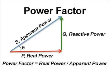
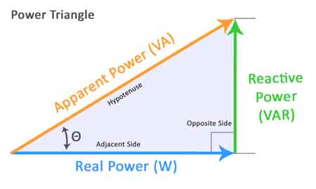
The power triangle is not a teaching diagram. It is a decision model.
Real power represents productive output.
Reactive power represents field-sustaining circulation.
Apparent power represents the total system burden.
The phase angle between voltage and current determines how much of the system’s delivered capacity is productive versus circulatory. This ratio, expressed as power factor, defines whether a system is economically and electrically efficient or quietly overstressed. Engineers evaluating phase displacement must translate Q into an efficiency impact using power factor calculation, as reactive behavior directly influences utility billing and thermal loading.
Understanding this triangle is not about memorization. It is about recognizing that any increase in reactive flow consumes system headroom that could otherwise support productive load.
The base relationship remains:
Q = V × I × sin(φ)
Where φ is the phase displacement between voltage and current. Positive angles indicate inductive dominance; negative angles indicate capacitive dominance.
In three-phase systems, the relationship becomes:
Q = √3 × V × I × sin(φ)
The √3 factor reflects phase geometry, but the decision relevance remains unchanged: reactive power always consumes capacity without producing output.
Engineers do not use this formula to obtain a number. They use it to answer questions such as:
• Is the transformer properly sized for the actual apparent demand?
• Is the feeder operating near thermal limits despite low kW loading?
• Are utility penalties driven by reactive behavior rather than consumption?
• Will capacitor placement improve stability or introduce resonance risk?
These are not calculation questions. They are design and operational decisions.
When reactive values are expressed in kilovolt-amperes reactive, the scale becomes operationally visible. KVAR represents the amount of circulating field energy a system must continuously support.
Every KVAR added to a network increases current flow, increases the risk of voltage drop, and increases conductor heating. KVAR is therefore not a bookkeeping unit. It is a stress indicator.
Reducing KVAR reduces:
• Thermal loading
• Voltage instability
• Apparent demand charges
• Equipment oversizing pressure
Power factor reflects how effectively delivered current produces useful work. A low power factor means the system is carrying excess reactive power.
Correcting this condition does not change real energy consumption. It changes how efficiently the system transports that energy. Compensation decisions depend on how effectively reactive flow is counterbalanced through power factor correction rather than by reactive reduction alone.
Think you know Power Quality? Take our quick, interactive quiz and test your knowledge in minutes.
Power factor correction strategies use capacitive or controlled reactive injection to counterbalance inductive dominance. However, correction is not a blanket solution. Over-correction introduces leading conditions that can destabilize voltage regulation and create resonance risks.
For this reason, power factor decisions must be based on reactive power analysis, not on rule-of-thumb correction tables. Engineers evaluating correction strategies must interpret Q through system behavior rather than textbook thresholds.
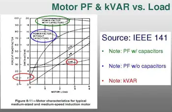
Induction motors are among the largest contributors to reactive power in industrial facilities. Their magnetic fields require reactive support, and their operating power factor changes with load.
Poor reactive management in motor systems leads to:
• Increased conductor heating
• Reduced voltage stability
• Inefficient transformer utilization
• Premature insulation stress
Motor reactive behavior must therefore be interpreted in the context of motor power factor rather than isolated nameplate values.
Compensation devices such as capacitor banks, reactors, and static VAR compensators exist to restore balance between reactive demand and supply. Their purpose is not to improve a metric. Their purpose is to stabilize system behavior.
Improperly applied compensation can worsen harmonic distortion, introduce resonance, and destabilize protective coordination. Effective compensation requires an understanding of reactive power at the system level, not the component level.
Systems dominated by field-sustaining energy frequently exhibit capacitive or inductive imbalance, which becomes clearer when compared against capacitive load behavior in AC networks.
Reactive power is therefore not a correction target. It is a system-control variable.
The reactive power formula survives in modern engineering not because it is simple, but because it remains the most direct expression of how phase displacement transforms system burden.
It connects:
• Field physics
• Thermal limits
• Voltage behavior
• Utility billing exposure
• Equipment life
No AI summary can replace the judgment required to apply it correctly.
Reactive power is not an inefficiency. It is a structural property of AC systems that must be managed rather than eliminated.
Reactive power errors rarely cause immediate failure. They cause gradual stress, hidden inefficiency, and financial erosion. The reactive power formula provides engineers with a way to quantify and control that hidden burden before it becomes operational risk.
Understanding Q is not about solving for a number. It is about recognizing how much of your electrical system is working for you, and how much is merely circulating. Reactive power ultimately defines whether a facility experiences stable delivery or chronic disturbance within broader power quality management.
Advantages To Instructor-Led Training – Instructor-Led Course, Customized Training, Multiple Locations, Economical, CEU Credits, Course Discounts.
Request For QuotationWhether you would prefer Live Online or In-Person instruction, our electrical training courses can be tailored to meet your company's specific requirements and delivered to your employees in one location or at various locations.