Power Factor Formula - Understanding AC Circuits
By R.W. Hurst, Editor

Power Factor Training
Our customized live online or in‑person group training can be delivered to your staff at your location.

- Live Online
- 6 hours Instructor-led
- Group Training Available
Download Our OSHA 3075 Fact Sheet – Understanding Electrical Hazards in the Workplace

- Learn the effects of electric current on the human body
- Understand OSHA safety standards and protective devices
- Discover essential lockout/tagout and grounding practices
Power factor formula = Real Power (kW) ÷ Apparent Power (kVA). It measures how efficiently electrical power is converted into useful work output. A high power factor indicates efficient energy use, essential for industrial, commercial, and residential electrical systems.
What is a Power Factor Formula?
✅ Calculates energy efficiency by comparing real power (kW) to apparent power (kVA)
✅ Helps reduce energy costs and improve system performance
✅ Essential for managing power quality in industrial and commercial electrical systems
Power Quality Analysis Training
Request a Free Power Quality Training Quotation
A power factor formula helps determine how efficiently electrical energy is used. A higher ratio indicates better energy efficiency, lower losses, and lower costs. Power factor (PF) is a vital measurement in any AC electrical system. It indicates how much of the energy drawn from the supply is effectively used for productive work. A strong grasp of the power factor formula can lead to improved system design, enhanced equipment performance, and lower operational costs.
What Is the Power Factor Formula?
At its core, the power factor formula is:
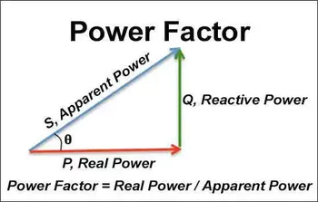
Power Factor (PF) = Real Power (kW) ÷ Apparent Power (kVA)
Real power performs actual work, while apparent power represents the combination of real and reactive components flowing through the electrical system. A ratio closer to 1.0 indicates maximum efficiency.
PF = cos(θ) is another way to express it, where θ (theta) is the phase angle between the voltage and current waveforms. The smaller the phase shift, the closer the PF is to 1.
For a full understanding of related concepts, you can see our detailed page on what is power factor.
Power Factor Formula Summary Table
| Term | Symbol | Meaning | Units |
|---|---|---|---|
| Real Power | P | The actual power consumed by equipment to do useful work, like turning a motor or lighting. | Watts (W) |
| Apparent Power | S | The total power supplied to a circuit, combining both real and reactive power. | Volt-amperes (VA) |
| Reactive Power | Q | The power that flows back and forth, stored and released by inductors and capacitors. | Volt-amperes reactive (var) |
| Power Factor | PF | The ratio of real power to apparent power measures the efficiency of power use. | No unit (value from 0–1) |
| Phase Angle | θ (theta) | The angle between the voltage and current waveforms is related to the power factor. | Degrees (°) |
| Power Factor (Angle Method) | PF | Describes power factor as the cosine of the phase angle between current and voltage. | No unit |
| Power Triangle | – | A visual model showing how real, reactive, and apparent power relate as sides of a triangle. | – |
| Distortion Factor | – | Accounts for waveform distortion from harmonics, reducing true power factor. | No unit |
PF Example Calculation
Let's walk through a real-world example:
-
Real Power (P) = 100 kW
-
Apparent Power (S) = 125 kVA
Using the formula:
PF = 100 ÷ 125 = 0.8
This means the system is operating at 80% efficiency, with 20% of the supplied energy lost due to reactive components like inductance.
Sign Up for Electricity Forum’s Power Quality Newsletter
Stay informed with our FREE Power Quality Newsletter — get the latest news, breakthrough technologies, and expert insights, delivered straight to your inbox.
For more detailed examples, visit our guide on how to calculate power factor.
Example:
If the phase shift is 30°, the PF is cos(30°) ≈ 0.866.
Learn more about phase shift effects on energy use at leading vs lagging power factor.
Understanding the Power Triangle
The Power Triangle is a visual representation showing the relationship between:
-
Real Power (kW) – horizontal side
-
Reactive Power (kVAR) – vertical side
-
Apparent Power (kVA) – hypotenuse
This triangle illustrates why PFC is essential in improving efficiency. If you're considering system upgrades, learn about power factor correction.
For more insight, explore our article on what is power factor.
Real-World Example
Suppose an industrial motor draws 100 kW of real power and 125 kVA of apparent power.
Applying the formula:
PF = 100 ÷ 125 = 0.8
This means the system operates at 80% efficiency, and 20% of the electrical energy is wasted due to reactive components. For further applications, check out our power factor calculator.
Why Improving Your Power Factor Matters
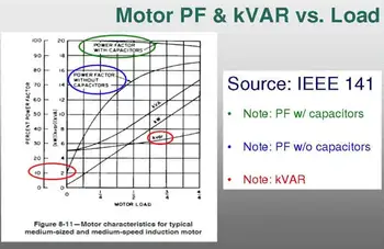
A poor ratio can lead to increased demand charges, wasted energy, and penalties from utility companies. Strategies such as installing capacitors, utilizing synchronous condensers, and implementing dynamic correction systems can enhance performance. If you're interested, see our power factor correction capacitor guide.
Dynamic adjustment technologies, as explained in our article on the automatic power factor controller, offer advanced methods for maintaining optimal performance even under changing load conditions.
Common Causes of Low PF
Several factors can decrease system efficiency:
-
Large inductive loads (motors, transformers)
-
Poor load management techniques
-
Increased reactive power from outdated equipment
To explore how inductive loads impact system performance, visit our page on lagging power factor.
Frequently Asked Questions
Why is cos(θ) important in the power factor formula?
It mathematically shows the phase difference between current and voltage, offering a precise measure of efficiency.
What devices can improve PF?
Capacitor banks, synchronous condensers, and advanced dynamic controllers all help correct imbalances.
How do I measure my facility’s PF?
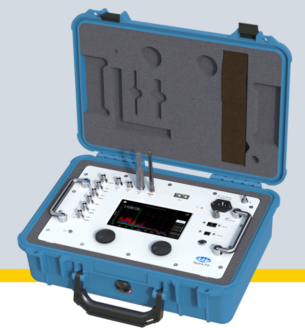
You can use handheld meters or multifunction analyzers, or refer to our comprehensive guide on calculating power factor.
Is there a difference between leading and lagging PF?
Yes. Inductive loads cause lagging, while capacitive loads may cause leading. Visit our 'Leading vs. Lagging Power Factor' page for a comprehensive explanation.
Why does PFC improve my utility bills?
By reducing wasted energy, you avoid extra utility charges and optimize system performance, as explained in our power factor correction examples.
Related Articles


