How to Calculate Power Factor in AC Circuits
By R.W. Hurst, Editor
By R.W. Hurst, Editor
Our customized live online or in‑person group training can be delivered to your staff at your location.


How to calculate power factor means dividing real power by apparent power, but the real engineering issue is what the result changes. A low PF raises current, increases heating, loads transformers and feeders, reduces available capacity, and can trigger utility penalties or correction decisions.
Power factor is calculated as PF = kW ÷ kVA, but the engineering decision starts after the formula is solved. The real question is whether a low value reflects normal reactive loading, a correction needed, a distorted waveform, or a system condition that is increasing current and consuming available capacity.
In plant and utility environments, a weak power factor is rarely just a number on a meter. It raises current for the same useful output, affects transformer and feeder loading, increases heating, reduces headroom for expansion, and can push a facility toward correction equipment it may not actually need. A facility can look stable on kW demand while still wasting usable system capacity because reactive current is circulating through conductors and equipment.
A low PF reading only becomes useful when it changes a real operating decision. If it is misunderstood, a team may add capacitors in the wrong location, mask a harmonic problem, or misread a motor load condition as a simple correction issue. On a large three-phase system, even a modest PF drop can increase current for the same useful output, and that increase is what creates the operational consequence.
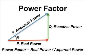
The standard formula is PF = kW ÷ kVA. Real power is the portion doing useful work. Apparent power is the combined effect of real and reactive demand seen by the source. In a balanced three-phase circuit, kVA is commonly calculated from voltage and current, whereas in single-phase circuits, it is calculated using the simpler V × I relationship. Apparent Power defines the supply burden, and Apparent Power vs Real Power shows why the ratio matters in operation.
Stay informed with our FREE Power Quality Newsletter — get the latest news, breakthrough technologies, and expert insights, delivered straight to your inbox.
In AC electrical systems, power factor PF is the ratio of real power to apparent power and shows how effectively supplied power is converted into useful output. Active power, also called working power, performs the actual work, while reactive power supports magnetic and electric fields in equipment such as motors and transformers.
Poor power factor is commonly associated with inductive loads, which create a lagging power factor and increase current for the same useful output. In some cases, capacitive loads or overcorrection can push the system in the opposite direction. Understanding this relationship is essential for improving energy efficiency, reducing unnecessary loading, and deciding whether correction is actually needed.
For single-phase systems, apparent power is V × I ÷ 1000. For three-phase systems, it is V × I × √3 ÷ 1000. A wrong voltage basis, an incorrect current reading, or a line-to-neutral versus line-to-line mix-up will distort the PF result before any correction decision is made. Three Phase Power Calculation and 3 Phase Power Formula are the right checks when the supply configuration is unclear.
Assume a three-phase load measures 300 kW at 400 V and 500 A. Apparent power is 400 × 500 × √3 ÷ 1000, or about 346 kVA. Power factor is then 300 ÷ 346, which equals 0.87.
That number is not the endpoint. A PF of 0.87 may be acceptable in one facility, but in another it can coincide with transformer heating, voltage-drop complaints, or tariff penalties, depending on the loading profile, billing thresholds, and whether the condition is persistent or confined to certain operating periods. When a faster check is needed, a Power Factor Calculator can speed up the arithmetic, but the interpretation still requires engineering judgment.
Many sites treat 0.90 or 0.95 as a target, but the correct threshold depends on the utility tariff, the load mix, and the operating pattern. That is the tradeoff. Aggressive correction can reduce current and penalty exposure, but overcorrection can create leading conditions at light load or interact badly with harmonics.
A low PF value does not automatically justify capacitor installation, because correcting a harmonic-rich system can shift the problem from excess current to resonance risk. Power Factor Correction should be evaluated with the Automatic Power Factor Controller logic when the load swings throughout the day.
The basic ratio assumes the measured kW and kVA represent the actual waveform condition. Nonlinear loads, variable-frequency drives, and harmonic distortion can make a site appear to have a correction problem when the deeper issue is waveform distortion rather than a simple displacement between voltage and current. In that case, capacitor installation alone may not resolve the operating issue and can sometimes worsen exposure to resonance.
Power Quality and Harmonics and Total Harmonic Distortion matter when the PF number does not match observed system behaviour.
A good PF calculation helps determine whether the next action should be monitoring, correction, load redistribution, or deeper troubleshooting. When PF falls, current rises for the same kW output, and that higher current can cascade into conductor heating, transformer loading, voltage drop, nuisance trips, and reduced spare capacity for expansion.
If you do not know whether the low value comes from reactive demand, distorted current, or shifting motor load, you are not ready to prescribe equipment. Motor Power Factor is often the better next step when rotating equipment dominates the profile.

A weak PF reading is not just a formula result. It is a warning that the system may be carrying more current than necessary, losing capacity it cannot afford to lose, or heading toward the wrong correction decision if the cause is not identified first.
Explore 50+ live, expert-led electrical training courses –