Latest Overhead T&D Articles
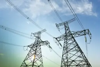
High Voltage AC Transmission Lines
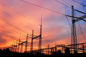
Ac transmission lines deliver alternating current across the power grid using high voltage, overhead conductors, and insulators, controlling reactive power, impedance, and corona effects to minimize losses, improve efficiency, and ensure reliable long-distance electricity transmission.
Understanding the Role of AC Transmission Lines in Power Systems
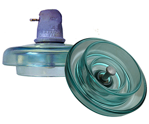
Three-phase electric power systems are used for high and extra-high voltage AC transmission lines (50kV and above). The pylons must therefore be designed to carry three (or multiples of three) conductors. The towers are usually steel lattices or trusses (wooden structures are used in Germany in exceptional cases) and the insulators are generally glass…
View more
Sign Up for Electricity Forum’s Overhead T&D Newsletter
Stay informed with our FREE Overhead T&D Newsletter — get the latest news, breakthrough technologies, and expert insights, delivered straight to your inbox.

Understanding How Overhead Switchgear Innovation Cost-Effectively
How Overhead Switchgear Innovation Cost Effectively? Advanced medium-voltage reclosers, vacuum interrupters, and SCADA-enabled smart sensors enhance reliability, reduce arc-flash risk, cut lifecycle maintenance, and optimize distribution networks for grid modernization and predictive maintenance.
How Overhead Switchgear Innovation Cost Effectively?
BACKGROUND
Achieving many of the globe’s top priorities depends on an unprecedented expansion of electric generation capacity. A report released last year by the Electric Power Research Institute (EPRI), for example, forecast that achieving net-zero carbon emissions in the U.S. by mid-century would require a nearly 500 percent increase in electricity generating capacity.
A decarbonized future powered largely by renewable…
View more
Electrical Distribution System
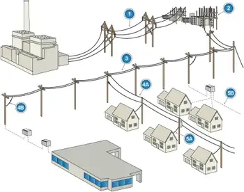
An electrical distribution system is the portion of the electric power grid that delivers electricity from distribution substations to end users through feeders, transformers, and service connections operating at medium and low voltage levels. It forms the physical link between transmission supply and electrical utilization by stepping voltage down and distributing it across local networks.
The system connects substations to loads through primary feeders and secondary circuits, which carry power from medium voltage networks to low voltage service points. This relationship defines how electrical energy moves from a bulk supply into a usable form without describing operational control or delivery…
View more
What is a Microgrid?
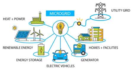
A microgrid is a localized energy system that can operate independently of or in conjunction with the main grid. By integrating renewable energy, storage, and smart controls, it enhances reliability, supports sustainability, and provides backup power for critical facilities.
What is a Microgrid?
Microgrids are gaining popularity as reliable and efficient solutions for modern energy challenges. They are increasingly valuable as the world pursues cleaner energy sources, carbon reduction, and grid modernization. By complementing smart grid infrastructure, they improve system reliability while helping communities and industries adapt to the demands of today’s evolving power networks.
What Defines…
View more

When it Comes To Digital Marketing, Novice Sailors Can Navigate Calm Waters But Rough Seas Require Expert Sailors...
Digital Marketing Tip: leverage SEO, content marketing, PPC, social media, and analytics to drive qualified traffic, improve engagement, increase conversion rates, and optimize ROI through data-driven testing, segmentation, and continuous optimization.
Digital Marketing Tip Explained
Yes, the current business storm is increasingly difficult to navigate because of the Covid-19 pandemic. So, why is it a bad time to cut your advertising budget?History has a great way of teaching us lessons. During tough economic times, it might seem logical to make cuts to your advertising budget, but in reality, that’s not a sound idea, as it actually hurts your business.…
View more
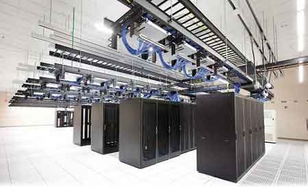
Data Center Power Distribution for Critical Load Reliability
Data center power distribution delivers conditioned electricity through switchgear, UPS systems, generators, PDUs, busway, and rack circuits so critical IT loads remain online during faults, maintenance isolation, transfer events, harmonic stress, and branch overloads.
Data center power distribution determines whether electrical disturbances remain local or cascade into service interruption. The objective is not simply to move electricity into a facility but to maintain continuous power delivery through switchgear, UPS systems, generators, PDUs, busway, and rack circuits, even when faults, maintenance isolation, or transfer events occur.
Critical computing loads cannot tolerate long recovery windows. A distribution architecture that appears redundant during…
View more
Overhead T&D, Direct Current Technology
Direct current technology delivers efficient DC power distribution via rectifiers, converters, and power electronics, enabling microgrids, energy storage, HVDC links, photovoltaics, and electric vehicle charging with reduced losses and improved reliability.
Direct Current Technology Fundamentals
Direct current (DC) is the preferred technology for moving large amounts of power across long distances. DC results in higher overall efficiency and reliability than an equivalently sized alternating current (AC) system moving the same amount of power.
The Advantages of DC
More efficient: Over long distances, DC transmission can move more power with less electrical losses than an equivalent AC transmission line. For…
View more