The Distribution Transformer and Grid Reliability
By Howard Williams, Associate Editor
By Howard Williams, Associate Editor
Our customized live online or in‑person group training can be delivered to your staff at your location.

A distribution transformer performs the final voltage transformation between primary distribution feeders and customer electrical service. Installed along overhead and underground feeders, these units convert medium-voltage distribution power into the lower service voltages used by homes, commercial buildings, and light industrial equipment.
Once power leaves the substation, the distribution transformer becomes the last device that determines how electricity actually reaches end users. Lighting systems, HVAC equipment, motors, and electronic loads all draw power through the same windings, meaning the unit must absorb constant changes in demand throughout the day.
This role extends well beyond simple voltage reduction. Load variation, phase imbalance, harmonic distortion, and cooling limits influence how heat accumulates inside the core and windings. Over time, these operating conditions shape how quickly insulation ages and how much thermal margin remains available during peak demand.
Because a distribution transformer sits at the boundary between utility infrastructure and customer equipment, its operating margin directly affects service voltage stability and feeder reliability. When loading, cooling performance, or phase balance drift outside normal limits, insulation deterioration accelerates and the risk of equipment failure or customer outages increases.
A distribution transformer converts medium-voltage feeder power into the secondary voltages required by customer equipment. Primary distribution voltages commonly range from roughly 4 kV to 35 kV, while secondary voltages typically include 120/240 V for residential service and 480 V for commercial or light industrial loads.
This voltage conversion occurs thousands of times across a utility service territory. Each transformer effectively becomes the final control point at which feeder-voltage conditions translate into customer-voltage quality.
Download our FREE Electrical Training Catalog and explore a full range of expert-led electrical training courses.

Utilities, therefore, evaluate distribution transformers not simply as electrical devices but as voltage-delivery assets. If loading or cooling margins shrink too far, service voltage can sag during peak demand or fluctuate under changing load conditions.
The broader system context for these units is described in the overview of Utility Transformers, where a distribution transformer represents the final interface between feeder networks and end-use electrical systems.
A distribution transformer is part of the power distribution system and is designed to reduce primary feeder voltage to usable service levels for homes and businesses. Most utility units are liquid-immersed units that use insulating oil to provide both electrical insulation and cooling for the windings.
In underground distribution networks, pad-mounted transformers are commonly used to supply nearby buildings, while some installations may use dry-type transformers where indoor placement or fire safety requirements limit the use of oil-filled equipment.
Voltage ratios define how feeder voltage becomes usable service voltage. Common ratios include:
• 13.8 kV to 120/240 V residential service
• 13.8 kV to 480 V commercial supply
• 4.16 kV to 208/120 V building distribution
Distribution transformer ratings typically range from about 10 kVA for small residential loads to more than 2,500 kVA for large commercial installations.
These ratings establish nominal capacity, but actual operating stress depends on load variation, phase balance, and cooling performance. Even moderate peak-demand events can produce localized heating within the windings that accelerates insulation deterioration.
The electromagnetic principles that allow voltage to be induced between the primary and secondary windings are explained in How Do Transformers Work, where magnetic flux in the core induces voltage in the secondary conductors.
Heat remains the primary factor in controlling the lifespan of distribution transformers. Copper losses in the windings and magnetic losses in the core convert electrical energy into heat that must be dissipated through cooling surfaces and insulating fluids.
When distribution transformer loading approaches thermal limits, winding temperature rises, and insulation aging accelerates. The degradation rate of cellulose insulation roughly doubles for every 6 to 7 °C increase above its design temperature limit.
This means that repeated short overload periods can significantly shorten the unit's life, even if the unit rarely exceeds its nameplate rating.
Cooling performance, therefore, becomes critical. Liquid-filled transformers rely on insulating oil to transfer heat from the windings to the tank walls, where it dissipates into the surrounding air. The behavior of these insulating fluids is explored in Transformer Oil, where oil circulation and thermal conductivity influence allowable loading.
Distribition transformer location along a feeder directly affects voltage performance. Units installed near the end of long distribution feeders may experience greater voltage drop during heavy demand because upstream conductors already carry substantial current.
When the feeder voltage drops, the distribution transformer must draw higher current to maintain secondary voltage levels. This increases internal heating and narrows the available thermal margin.
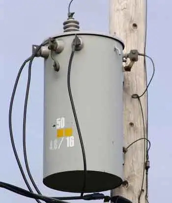
Pole-mounted units are widely used in overhead distribution systems because elevated mounting improves natural air circulation and cooling performance. Operational considerations for these installations are described in Pole Mounted Transformers, where weather exposure and airflow influence thermal behavior.
In underground networks, utilities often rely on enclosure designs such as those discussed in Padmount Transformer, where limited airflow and warmer ground environments can reduce cooling effectiveness.

Modern electrical systems introduce increasing levels of harmonic distortion through electronic loads such as variable-speed drives, switching power supplies, and inverter-based equipment.
These nonlinear loads distort current waveforms and increase winding heating. When combined with uneven phase loading, harmonic currents can cause localized overheating even when the unit appears to operate within its rated capacity.
Three-phase distribution systems are particularly sensitive to this condition because circulating currents may develop between windings and neutral conductors. The electrical relationships that govern this behavior are examined in 3 Phase Transformers, where phase balance determines how current is distributed across windings.
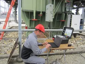
Distribution transformer deterioration usually develops slowly, which makes condition monitoring important for asset management programs. Utilities track temperature, load patterns, and dissolved gases in insulating oil to detect early signs of insulation breakdown.
Monitoring also helps engineers identify units that operate near thermal limits due to load growth or feeder reconfiguration. Predictive approaches described in Condition Monitoring In An Age Of Modernization allow utilities to detect emerging problems before catastrophic failure occurs.
Sizing decisions involve tradeoffs. Oversizing a distribution transformer increases thermal margin and voltage stability but raises capital cost and may reduce efficiency when loads remain light for long periods.
Undersizing reduces upfront investment but exposes the unit to higher operating stress during peak demand, accelerating insulation aging and increasing the likelihood of early replacement.
Emerging distributed energy resources introduce another operational edge case. Rooftop solar installations can push power back through a distribution transformer during low-demand periods, reversing the normal direction of power flow. When this occurs, voltage regulation equipment and thermal behavior may respond differently than originally expected.
Although relatively small compared with transmission equipment, distribution transformers define the operational boundary of the electrical grid. They translate feeder-voltage conditions, load behavior, and harmonic distortion into the service voltage customers actually receive.
When the distribution transformer operates within thermal and electrical limits, voltage delivery remains stable, and insulation aging progresses slowly. When loading, cooling limitations, or phase imbalance exceed design expectations, deterioration accelerates, and voltage quality can begin to decline.
For utilities and system operators, the condition of distribution transformers therefore provides a direct indicator of grid health. Their operating margins reveal whether feeder networks maintain sufficient capacity or whether cumulative electrical stress is quietly eroding reliability at the edge of the distribution system.
Explore 50+ live, expert-led electrical training courses –