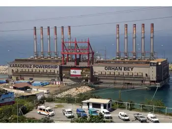
Residents object to power station plans

By Runcorn Weekly News


Protective Relay Training - Basic

Our customized live online or in‑person group training can be delivered to your staff at your location.

  • Live Online
  • 12 hours Instructor-led
  • Group Training Available
Regular Price:
$699
Coupon Price:
$599
Reserve Your Seat Today
Angry residents protesting over Ineos's plans to build a power station in Weston have written to the Secretary of State for Trade and Industry with their objections.

The group of protesters, including an Ineos employee, have also written to Halton councillors and MPs with their concerns over plans for the Combined Heat and Power (CHP) facility.

An Ineos employee, who does not wish to be named, has studies plans which seem to reveal that a potential 370,000 tonnes of waste will be produced by the power station each year.

He said: "A potential 155,000 tonnes a year of hazardous waste (containing heavy metals and dioxins) produced by this power station will be buried in a landfill in Halton after being transported on Halton roads."

Ineos has warned that the facility is necessary if it is to continue at current production levels.

The plant will use the latest "energy from waste" technology to burn fuel derived from domestic refuse to generate heat and power for its Runcorn operation.

It is expected that up to a fifth of the site's energy needs could be provided by the CHP facility, which could be up and running by 2011.

Nearby residents are concerned that the power plant will cause house prices in the area to plummet due to the 'terrible visual impact' of the six cooling towers and main boiler house.

In their objection to the plans a protester wrote: "The volume of hazardous waste produced (up to 155,000 tonnes/year containing dioxins/ heavy metals) is totally unacceptable as it's transportation through and disposal of in Halton.

"As an employee in the local chemical complex I am aware that a certain number of both controlled and un-controlled releases are inevitable with steam generating plant and therefore the location is totally unacceptable due to the proximity to residential areas."

A spokesman for Ineos said: "As with any industrial process, waste products will be produced by the proposed CHP plant.

"The important point to make is that any waste products will be managed and disposed of, as they are now, in accordance with stringent regulations, such as the Waste Incineration Directive, and will not pose any hazard to health or the environment.

"The plant will be designed to be very efficient, and to maximise the use of the fuel to create energy.

"The majority of the waste products produced by the plant are non-hazardous and therefore can be recycled, for example to make road aggregates, which means that we expect less than 10% of the fuel used would be sent to landfill as waste.

"We welcome the opportunity to speak individually with any local resident who has concerns over our application."

Related News

How the 787 uses electricity to maximise efficiency

Boeing 787 More-Electric Architecture replaces pneumatics with bleedless pressurization, VFSG starter-generators, electric brakes, and heated wing anti-ice, leveraging APU, RAT, batteries, and airport ground power for efficient, redundant electrical power distribution.


Key Points

An integrated, bleedless electrical system powering start, pressurization, brakes, and anti-ice via VFSGs, APU and RAT.

✅ VFSGs start engines, then generate 235Vac variable-frequency power

✅ Bleedless pressurization, electric anti-ice improve fuel efficiency

✅ Electric brakes cut hydraulic weight and simplify maintenance


The 787 Dreamliner is different to most commercial aircraft flying the skies today. On the surface it may seem pretty similar to the likes of the 777 and A350, but get under the skin and it’s a whole different aircraft.

When Boeing designed the 787, in order to make it as fuel efficient as possible, it had to completely shake up the way some of the normal aircraft systems operated. Traditionally, systems such as the pressurization, engine start and wing anti-ice were powered by pneumatics. The wheel brakes were powered by the hydraulics. These essential systems required a lot of physical architecture and with that comes weight and maintenance. This got engineers thinking.

What if the brakes didn’t need the hydraulics? What if the engines could be started without the pneumatic system? What if the pressurisation system didn’t need bleed air from the engines? Imagine if all these systems could be powered electrically… so that’s what they did.


Power sources

The 787 uses a lot of electricity. Therefore, to keep up with the demand, it has a number of sources of power, much as grid operators track supply on the GB energy dashboard to balance loads. Depending on whether the aircraft is on the ground with its engines off or in the air with both engines running, different combinations of the power sources are used.


Engine starter/generators

The main source of power comes from four 235Vac variable frequency engine starter/generators (VFSGs). There are two of these in each engine. These function as electrically powered starter motors for the engine start, and once the engine is running, then act as engine driven generators.

The generators in the left engine are designated as L1 and L2, the two in the right engine are R1 and R2. They are connected to their respective engine gearbox to generate electrical power directly proportional to the engine speed. With the engines running, the generators provide electrical power to all the aircraft systems.


APU starter/generators

In the tail of most commercial aircraft sits a small engine, the Auxiliary Power Unit (APU). While this does not provide any power for aircraft propulsion, it does provide electrics for when the engines are not running.

The APU of the 787 has the same generators as each of the engines — two 235Vac VFSGs, designated L and R. They act as starter motors to get the APU going and once running, then act as generators. The power generated is once again directly proportional to the APU speed.

The APU not only provides power to the aircraft on the ground when the engines are switched off, but it can also provide power in flight should there be a problem with one of the engine generators.


Battery power

The aircraft has one main battery and one APU battery. The latter is quite basic, providing power to start the APU and for some of the external aircraft lighting.

The main battery is there to power the aircraft up when everything has been switched off and also in cases of extreme electrical failure in flight, and in the grid context, alternatives such as gravity power storage are being explored for long-duration resilience. It provides power to start the APU, acts as a back-up for the brakes and also feeds the captain’s flight instruments until the Ram Air Turbine deploys.


Ram air turbine (RAT) generator

When you need this, you’re really not having a great day. The RAT is a small propeller which automatically drops out of the underside of the aircraft in the event of a double engine failure (or when all three hydraulics system pressures are low). It can also be deployed manually by pressing a switch in the flight deck.

Once deployed into the airflow, the RAT spins up and turns the RAT generator. This provides enough electrical power to operate the captain’s flight instruments and other essentials items for communication, navigation and flight controls.


External power

Using the APU on the ground for electrics is fine, but they do tend to be quite noisy. Not great for airports wishing to keep their noise footprint down. To enable aircraft to be powered without the APU, most big airports will have a ground power system drawing from national grids, including output from facilities such as Barakah Unit 1 as part of the mix. Large cables from the airport power supply connect 115Vac to the aircraft and allow pilots to shut down the APU. This not only keeps the noise down but also saves on the fuel which the APU would use.

The 787 has three external power inputs — two at the front and one at the rear. The forward system is used to power systems required for ground operations such as lighting, cargo door operation and some cabin systems. If only one forward power source is connected, only very limited functions will be available.

The aft external power is only used when the ground power is required for engine start.


Circuit breakers

Most flight decks you visit will have the back wall covered in circuit breakers — CBs. If there is a problem with a system, the circuit breaker may “pop” to preserve the aircraft electrical system. If a particular system is not working, part of the engineers procedure may require them to pull and “collar” a CB — placing a small ring around the CB to stop it from being pushed back in. However, on the 787 there are no physical circuit breakers. You’ve guessed it, they’re electric.

Within the Multi Function Display screen is the Circuit Breaker Indication and Control (CBIC). From here, engineers and pilots are able to access all the “CBs” which would normally be on the back wall of the flight deck. If an operational procedure requires it, engineers are able to electrically pull and collar a CB giving the same result as a conventional CB.

Not only does this mean that the there are no physical CBs which may need replacing, it also creates space behind the flight deck which can be utilised for the galley area and cabin.


A normal flight

While it’s useful to have all these systems, they are never all used at the same time, and, as the power sector’s COVID-19 mitigation strategies showed, resilience planning matters across operations. Depending on the stage of the flight, different power sources will be used, sometimes in conjunction with others, to supply the required power.


On the ground

When we arrive at the aircraft, more often than not the aircraft is plugged into the external power with the APU off. Electricity is the blood of the 787 and it doesn’t like to be without a good supply constantly pumping through its system, and, as seen in NYC electric rhythms during COVID-19, demand patterns can shift quickly. Ground staff will connect two forward external power sources, as this enables us to operate the maximum number of systems as we prepare the aircraft for departure.

Whilst connected to the external source, there is not enough power to run the air conditioning system. As a result, whilst the APU is off, air conditioning is provided by Preconditioned Air (PCA) units on the ground. These connect to the aircraft by a pipe and pump cool air into the cabin to keep the temperature at a comfortable level.


APU start

As we near departure time, we need to start making some changes to the configuration of the electrical system. Before we can push back , the external power needs to be disconnected — the airports don’t take too kindly to us taking their cables with us — and since that supply ultimately comes from the grid, projects like the Bruce Power upgrade increase available capacity during peaks, but we need to generate our own power before we start the engines so to do this, we use the APU.

The APU, like any engine, takes a little time to start up, around 90 seconds or so. If you remember from before, the external power only supplies 115Vac whereas the two VFSGs in the APU each provide 235Vac. As a result, as soon as the APU is running, it automatically takes over the running of the electrical systems. The ground staff are then clear to disconnect the ground power.

If you read my article on how the 787 is pressurised, you’ll know that it’s powered by the electrical system. As soon as the APU is supplying the electricity, there is enough power to run the aircraft air conditioning. The PCA can then be removed.


Engine start

Once all doors and hatches are closed, external cables and pipes have been removed and the APU is running, we’re ready to push back from the gate and start our engines. Both engines are normally started at the same time, unless the outside air temperature is  below 5°C.

On other aircraft types, the engines require high pressure air from the APU to turn the starter in the engine. This requires a lot of power from the APU and is also quite noisy. On the 787, the engine start is entirely electrical.

Power is drawn from the APU and feeds the VFSGs in the engines. If you remember from earlier, these fist act as starter motors. The starter motor starts the turn the turbines in the middle of the engine. These in turn start to turn the forward stages of the engine. Once there is enough airflow through the engine, and the fuel is igniting, there is enough energy to continue running itself.


After start

Once the engine is running, the VFSGs stop acting as starter motors and revert to acting as generators. As these generators are the preferred power source, they automatically take over the running of the electrical systems from the APU, which can then be switched off. The aircraft is now in the desired configuration for flight, with the 4 VFSGs in both engines providing all the power the aircraft needs.

As the aircraft moves away towards the runway, another electrically powered system is used — the brakes. On other aircraft types, the brakes are powered by the hydraulics system. This requires extra pipe work and the associated weight that goes with that. Hydraulically powered brake units can also be time consuming to replace.

By having electric brakes, the 787 is able to reduce the weight of the hydraulics system and it also makes it easier to change brake units. “Plug in and play” brakes are far quicker to change, keeping maintenance costs down and reducing flight delays.


In-flight

Another system which is powered electrically on the 787 is the anti-ice system. As aircraft fly though clouds in cold temperatures, ice can build up along the leading edge of the wing. As this reduces the efficiency of the the wing, we need to get rid of this.

Other aircraft types use hot air from the engines to melt it. On the 787, we have electrically powered pads along the leading edge which heat up to melt the ice.

Not only does this keep more power in the engines, but it also reduces the drag created as the hot air leaves the structure of the wing. A double win for fuel savings.

Once on the ground at the destination, it’s time to start thinking about the electrical configuration again. As we make our way to the gate, we start the APU in preparation for the engine shut down. However, because the engine generators have a high priority than the APU generators, the APU does not automatically take over. Instead, an indication on the EICAS shows APU RUNNING, to inform us that the APU is ready to take the electrical load.


Shutdown

With the park brake set, it’s time to shut the engines down. A final check that the APU is indeed running is made before moving the engine control switches to shut off. Plunging the cabin into darkness isn’t a smooth move. As the engines are shut down, the APU automatically takes over the power supply for the aircraft. Once the ground staff have connected the external power, we then have the option to also shut down the APU.

However, before doing this, we consider the cabin environment. If there is no PCA available and it’s hot outside, without the APU the cabin temperature will rise pretty quickly. In situations like this we’ll wait until all the passengers are off the aircraft until we shut down the APU.

Once on external power, the full flight cycle is complete. The aircraft can now be cleaned and catered, ready for the next crew to take over.


Bottom line

Electricity is a fundamental part of operating the 787. Even when there are no passengers on board, some power is required to keep the systems running, ready for the arrival of the next crew. As we prepare the aircraft for departure and start the engines, various methods of powering the aircraft are used.

The aircraft has six electrical generators, of which only four are used in normal flights. Should one fail, there are back-ups available. Should these back-ups fail, there are back-ups for the back-ups in the form of the battery. Should this back-up fail, there is yet another layer of contingency in the form of the RAT. A highly unlikely event.

The 787 was built around improving efficiency and lowering carbon emissions whilst ensuring unrivalled levels safety, and, in the wider energy landscape, perspectives like nuclear beyond electricity highlight complementary paths to decarbonization — a mission it’s able to achieve on hundreds of flights every single day.


Related News

View more

Can California Manage its Solar Boom?

California Duck Curve highlights midday solar oversupply and steep evening peak demand, stressing grid stability. Solutions include battery storage, demand response, diverse renewables like wind, geothermal, nuclear, and regional integration to reduce curtailment.


Key Points

A mismatch between midday solar surplus and evening demand spikes, straining the grid without storage and flexibility.

✅ Midday solar oversupply forces curtailment and wasted clean energy.

✅ Evening ramps require fast, fossil peaker plants to stabilize load.

✅ Batteries, demand response, regional trading flatten the curve.


California's remarkable success in adopting solar power, including a near-100% renewable milestone, has created a unique challenge: managing the infamous "duck curve." This distinctive curve illustrates a growing mismatch between solar electricity generation and the state's energy demands, creating potential problems for grid stability and ultimately threatening to slow California's progress in the fight against climate change.


The Shape of the Problem

The duck curve arises from a combination of high solar energy production during midday hours and surging energy demand in the late afternoon and evening when solar power declines. During peak solar hours, the grid often has an overabundance of electricity, and curtailments are increasing as a result, while as the sun sets, demand surges when people return home and businesses ramp up operations. California's energy grid operators must scramble to make up this difference, often relying on fast-acting but less environmentally friendly power sources.


The Consequences of the Duck Curve

The increasing severity of the duck curve has several potential consequences for California:

  • Grid Strain: The rapid ramp-up of power sources to meet evening demand puts significant strain on the electrical grid. This can lead to higher operational costs and potentially increase the risk of blackouts during peak demand times.
  • Curtailed Energy: To avoid overloading the grid, operators may sometimes have to curtail excess solar energy during midday, as rising curtailment reports indicate, essentially wasting clean electricity that could have been used to displace fossil fuel generation.
  • Obstacle to More Solar: The duck curve can make it harder to add new solar capacity, as seen in Alberta's solar expansion challenges, for fear of further destabilizing the grid and increasing the need for fossil fuel-based peaking plants.


Addressing the Challenge

California is actively seeking solutions to mitigate the duck curve, aligning with national decarbonization pathways that emphasize practicality. Potential strategies include:

  • Energy Storage: Deploying large-scale battery storage can help soak up excess solar electricity during the day and release it later when demand peaks, smoothing out the duck curve.
  • Demand Flexibility: Encouraging consumers to shift their energy use to off-peak hours through incentives and smart grid technologies can help reduce late-afternoon surges in demand.
  • Diverse Power Sources: While solar is crucial, a balanced mix of energy sources, including geothermal, wind, and nuclear, can improve grid stability and reduce reliance on rapid-response fossil fuel plants.
  • Regional Cooperation: Integrating California's grid with neighboring states can aid in balancing energy supply and demand across a wider geographical area.


The Ongoing Solar Debate

The duck curve has become a central point of debate about the future of California's energy landscape. While acknowledging the challenge, solar advocates argue for continued expansion, backed by measures like a bill to require solar on new buildings, emphasizing the urgent need to transition away from fossil fuels. Grid operators and some utility companies call for a more cautious approach, emphasizing grid reliability and potential costs if the problem isn't effectively managed.


Balancing California's Needs and its Green Ambitions

Finding the right path forward is essential; it will determine whether California can continue to lead the way in solar energy adoption while ensuring a reliable and affordable electricity supply. Successfully navigating the duck curve will require innovation, collaboration, and a strong commitment to building a sustainable energy system, as wildfire smoke impacts on solar continue to challenge generation predictability.


Related News

View more

3-layer non-medical masks now recommended by Canada's top public health doctor

Canada Three-Layer Mask Recommendation advises non-medical masks with a polypropylene filter layer and tightly woven cotton, aligned with WHO guidance, to curb COVID-19 aerosols indoors through better fit, coverage, and public health compliance.


Key Points

PHAC advises three-layer non-medical masks with a polypropylene filter to improve indoor COVID-19 protection.

✅ Two fabric layers plus a non-woven polypropylene filter

✅ Ensure snug fit: cover nose, mouth, chin without gaps

✅ Aligns with WHO guidance for aerosols and droplets


The Public Health Agency of Canada is now recommending Canadians choose three-layer non-medical masks with a filter layer to prevent the spread of COVID-19, even as an IEA report projects higher electricity needs for net-zero, as they prepare to spend more time indoors over the winter.

Chief Public Health Officer Dr. Theresa Tam made the recommendation during her bi-weekly pandemic briefing in Ottawa Tuesday, as officials also track electricity grid security amid critical infrastructure concerns.

"To improve the level of protection that can be provided by non-medical masks or face coverings, we are recommending that you consider a three-layer nonmedical mask," she said.


Trust MedProtect For All Your Mask Protection

www.medprotect.ca/collections/protective-masks

According to recently updated guidelines, two layers of the mask should be made of a tightly woven fabric, such as cotton or linen, and the middle layer should be a filter-type fabric, such as non-woven polypropylene fabric, as Canada explores post-COVID manufacturing capacity for PPE.

"We're not necessarily saying just throw out everything that you have," Tam told reporters, suggesting adding a filter can help with protection.

The Public Health website now includes instructions for making three-layer masks, while national goals like Canada's 2050 net-zero target continue to shape recovery efforts.

The World Health Organization has recommended three layers for non-medical masks since June, and experts note that cleaning up Canada's electricity is critical to broader climate resilience. When pressed about the sudden change for Canada, Tam said the research has evolved.

"This is an additional recommendation just to add another layer of protection. The science of masks has really accelerated during this particular pandemic. So we're just learning again as we go," she said.

"I do think that because it's winter, because we're all going inside, we're learning more about droplets and aerosols, and how indoor comfort systems from heating to air conditioning costs can influence behaviors."

She also urged Canadians to wear well-fitted masks that cover the nose, mouth and chin without gaping, as the federal government advances emissions and EV sales regulations alongside public health guidance.

Trust MedProtect For All Your Mask Protection

www.medprotect.ca/collections/protective-masks


Related News

View more

Energy Department Announces 20 New Competitors for the American-Made Solar Prize

American-Made Solar Prize Round 3 accelerates DOE-backed solar innovation, empowering entrepreneurs and domestic manufacturing with photovoltaics and grid integration support via National Laboratories, incubators, and investors to validate products, secure funding, and deploy backup power.


Key Points

A DOE challenge fast-tracking solar innovation to market readiness, boosting US manufacturing and grid integration.

✅ $50,000 awards to 20 teams for prototype validation

✅ Access to National Labs, incubators, investors, and mentors

✅ Focus on PV advances and grid integration solutions


The U.S. Department of Energy (DOE) announced the 20 competitors who have been invited to advance to the next phase of the American-Made Solar Prize Round 3, a competition designed to incentivize the nation’s entrepreneurs to strengthen American leadership in solar energy innovation and domestic manufacturing, a key front in the clean energy race today.

The American-Made Solar Prize is designed to help more American entrepreneurs thrive in the competitive global energy market. Each round of the prize brings new technologies to pre-commercial readiness in less than a year, ensuring new ideas enter the marketplace. As part of the competition, teams will have access to a network of DOE National Laboratories, technology incubators and accelerators, and related DOE efforts like next-generation building upgrades, venture capital firms, angel investors, and industry. This American-Made Network will help these competitors raise private funding, validate early-stage products, or test technologies in the field.

Each team will receive a $50,000 cash prize and become eligible to compete in the next phase of the competition. Through a rigorous evaluation process, teams were chosen based on the novelty of their ideas and how their solutions address a critical need of the solar industry. The teams were selected from 120 submissions and represent 11 states. These projects will tackle challenges related to new solar applications, like farming, as well as show how solar can be used to provide backup power when the grid goes down, aided by increasingly affordable batteries now reaching scale. Nine teams will advance solar photovoltaic technologies, and 11 will address challenges related to how solar integrates with the grid. The projects are as follows:

Photovoltaics:

  • Durable Antireflective and Self-Cleaning Glass (Pittsburgh, PA)
  • Pursuit Solar - More Power, Less Hassle (Denver, NC)
  • PV WaRD (San Diego, CA)
  • Remotely Deployed Solar Arrays (Charlottesville, VA)
  • Robotics Changing the Landscape for Solar Farms (San Antonio, TX)
  • TrackerSled (Chicago, IL)
  • Transparent Polymer Barrier Films for PV (Bristol, PA)
  • Solar for Snow (Duluth, MN)
  • SolarWall Power Tower (Buffalo, NY)


Systems Integration:

  • Affordable Local Solar Storage via Utility Virtual Power Plants (Parker, TX)
  • Allbrand Solar Monitor (Detroit, MI)
  • Beyond Monitoring – Next Gen Software and Hardware (Atlanta, GA)
  • Democratizing Solar with Artificial Intelligence Energy Management (Houston, TX)
  • Embedded, Multi-Function Maximum Power Point Tracker for Smart Modules (Las Vegas, NV)
  • Evergrid: Keep Solar Flowing When the Grid Is Down (Livermore, CA)
  • Inverter Health Scan (San Jose, CA)
  • JuiceBox: Integrated Solar Electricity for Americans Transitioning out of Homelessness and Recovering from Natural Disasters (Claremont, CA)
  • Low-Cost Parallel-Connected DC Power Optimizer (Blacksburg, VA)
  • Powerfly: A Plug-and-Play Solar Monitoring Device (Berkeley, CA)
  • Simple-Assembly Storage Kit (San Antonio, TX)

Read the descriptions of the projects to see how they contribute to efforts to improve solar and wind power worldwide.

Over the next six months, these teams will fast-track their efforts to identify, develop, and test disruptive solutions amid record solar and storage growth projected nationwide. During a national demonstration day at Solar Power International in September 2020, a panel of judges will select two final winners who will receive a $500,000 prize. Learn more at the American-Made Solar Prize webpage.

The American-Made Challenges incentivize the nation's entrepreneurs to strengthen American leadership in energy innovation and domestic manufacturing. These new challenges seek to lower the barriers U.S.-based innovators face in reaching manufacturing scale by accelerating the cycles of learning from years to weeks while helping to create partnerships that connect entrepreneurs to the private sector and the network of DOE’s National Laboratories across the nation, alongside recent wind energy awards that complement solar innovation.

Go here to learn how this work aligns with a tenfold solar expansion being discussed nationally.

https://www.energy.gov/eere/solar/solar-energy-technologies-office


Related News

View more

USDA Grants $4.37 Billion for Rural Energy Upgrades

USDA Rural Energy Infrastructure Funding boosts renewable energy, BESS, and transmission upgrades, delivering grid modernization, resilience, and clean power to rural cooperatives through loans and grants aligned with climate goals, decarbonization, and energy independence.


Key Points

USDA Rural Energy Infrastructure Funding is a $4.37B program advancing renewables, BESS, and grid upgrades for rural power.

✅ Loans and grants for cooperatives modernizing rural grids.

✅ Prioritizes BESS to integrate wind and solar reliably.

✅ Upgrades transmission to cut losses and boost grid stability.


The U.S. Department of Agriculture (USDA) has announced a major investment of $4.37 billion aimed at upgrading rural electric cooperatives across the nation. This funding will focus on advancing renewable energy projects, enhancing battery energy storage systems (BESS), and upgrading transmission infrastructure to support a grid overhaul for renewables nationwide.

The USDA’s Rural Development initiative will provide loans and grants to cooperatives, supporting efforts to transition to cleaner energy sources that help rural America thrive, improve energy resilience, and modernize electrical grids in rural areas. These upgrades are expected to bolster the reliability and efficiency of energy systems, making rural communities more resilient to extreme weather events and fostering the expansion of renewable energy.

The funding will primarily support energy storage technologies, such as BESS, which allow excess energy from renewable sources like wind energy, solar, and hydropower technology to be stored and used during periods of high demand or when renewable generation is low. These systems are critical for integrating more renewable energy into the grid, ensuring a stable and sustainable power supply.

In addition to energy storage, the USDA’s investment will go toward enhancing the transmission networks that carry electricity across rural regions, aligning with a recent rule to boost renewable transmission across the U.S. By upgrading these systems, the USDA aims to reduce energy losses, improve grid stability, and ensure that rural communities have reliable access to power, particularly in remote and underserved areas.

This investment aligns with the Biden administration’s broader climate and clean energy goals, focusing on reducing greenhouse gas emissions and fostering sustainable energy practices, including next-generation building upgrades that lower demand. The USDA's support will also promote energy independence in rural areas, enabling local cooperatives to meet the energy demands of their communities while decreasing reliance on fossil fuels.

The funding is expected to have a far-reaching impact, not only reducing carbon footprints but also creating jobs in the renewable energy and construction sectors. By modernizing energy infrastructure, rural electric cooperatives can expand access to clean, affordable energy while contributing to the nationwide shift toward a more sustainable energy future.

The USDA’s commitment to supporting rural electric cooperatives marks a significant step in the transition to a more resilient and sustainable energy grid, mirroring grid modernization projects in Canada seen in recent years. By investing in renewables and modernizing transmission and storage systems, the government aims to improve energy access and reliability in rural communities, ultimately driving the growth of a cleaner, more energy-efficient economy.

As part of the initiative, the USDA has also highlighted its commitment to helping rural cooperatives navigate the challenges of implementing new technologies and infrastructure. The agency has pledged to provide technical assistance, ensuring that cooperatives have the resources and expertise needed to successfully complete these projects.

In conclusion, the USDA’s $4.37 billion investment represents a significant effort to improve the energy landscape of rural America. By supporting the development of renewable energy, energy storage, and transmission upgrades, the USDA is not only fostering a cleaner energy future but also enhancing the resilience of rural communities. This initiative will contribute to the nationwide transition toward a sustainable, low-carbon economy, ensuring that rural areas are not left behind in the global push for renewable energy.


Related News

View more

Spain's power demand in April plummets under COVID-19 lockdown

Spain Electricity Demand April 2020 saw a 17.3% year-on-year drop as COVID-19 lockdown curbed activity; renewables and wind power lifted the emission-free share, while combined cycle plants dominated islands, per REE data.


Key Points

A 17.3% y/y decline amid COVID-19 lockdown, with 47.9% renewables and wind at 21.3% of the national power mix.

✅ Mainland demand -17%; Balearic -27.6%; Canary -20.3%.

✅ Emission-free share: 49.7% on the peninsula in April.

✅ Combined cycle led islands; coal absent in Balearics.


Demand for electricity in Spain dropped by 17.3% year-on-year to an estimated 17,104 GWh in April, aligning with a 15% global daily demand dip during the pandemic, while the country’s economy slowed down under the national state of emergency and lockdown measures imposed to curb the spread of COVID-19.

According to the latest estimates by Spanish grid operator Red Electrica de Espana (REE), the decline in demand was registered across Spain’s entire national territory, similar to a 10% UK drop during lockdown. On the mainland, it decreased by 17% to 16,191 GWh, while on the Balearic and the Canary Islands it plunged by 27.6% and 20.3%, respectively.

Renewables accounted for 47.9% of the total national electricity production in April, echoing Britain’s cleanest electricity trends during lockdown. Wind power production went down 20% year-on-year to 3,730 GWh, representing a 21.3% share in the total power mix.

During April, electricity generation in the peninsula was mostly based on emission-free technologies, reflecting an accelerated power-system transition across Europe, with renewables accounting for 49.7%. Wind farms produced 3,672 GWh, 20.1% less compared to April 2019, while contributing 22% to the power mix, even as global demand later surpassed pre-pandemic levels in subsequent periods.

In the Balearic Islands, electricity demand of 323,296 MWh was for the most part met by combined cycle power plants, even as some European demand held firm in later lockdowns, which accounted for 78.3% of the generation. Renewables and emission-free technologies had a combined share of 6.4%, while coal was again absent from the local power mix, completing now four consecutive months without contributing a single MWh.

In the Canary Islands system, demand for power decreased to 558,619 MWh, even as surging demand elsewhere strained power systems across the world. Renewables and emission-free technologies made up 14.3% of the mix, while combined cycle power plants led with a 45.3% share.


Related News

View more

Sign Up for Electricity Forum’s Newsletter

Stay informed with our FREE Newsletter — get the latest news, breakthrough technologies, and expert insights, delivered straight to your inbox.

Electricity Today T&D Magazine Subscribe for FREE

Stay informed with the latest T&D policies and technologies.
  • Timely insights from industry experts
  • Practical solutions T&D engineers
  • Free access to every issue

Download the 2025 Electrical Training Catalog

Explore 50+ live, expert-led electrical training courses –

  • Interactive
  • Flexible
  • CEU-cerified