How to Test a Solid State Relay?
By R.W. Hurst, Editor
By R.W. Hurst, Editor

Our customized live online or in‑person group training can be delivered to your staff at your location.


A solid state relay can fail without visible damage, leaving loads energized, unresponsive, or unstable. Testing confirms whether the control input, switching action, and output path respond correctly, helping prevent silent failures that cause equipment damage, control errors, or unexpected downtime.
Use a multimeter to test a solid state relay by checking the input voltage, output continuity, and switching function. When the correct control voltage is applied across the input terminals, the relay should change state and allow current to flow through the output. Regular testing helps detect early signs of failure and reduces the risk of unexpected system interruptions.
Solid state relays are durable switching devices, but thermal stress, overvoltage, and sustained load conditions can degrade their performance over time. Testing verifies that the relay still responds correctly under control input and load conditions, which is critical in systems where a failed SSR may not trip protection devices or show visible damage. A structured testing routine helps confirm functionality before failures escalate into process disruption or equipment damage.
A multimeter with continuity, diode, and resistance measurement functions
A controlled DC or AC power source for input signal simulation
A known load, such as a resistive lamp or heater, for output switching validation
An oscilloscope for observing switching timing, optional
A clamp meter or ammeter for current measurement
Basic Protection Relay Training
Request a Free Training Quotation
Solid state relays are critical components in many industrial and commercial control systems, offering silent, fast, and reliable switching. However, their solid-state nature means internal failures may not be immediately visible or audible, making regular testing essential. Without proactive testing, a faulty SSR could remain undetected until it causes a system malfunction or downtime. Understanding why SSR testing matters, and how it contributes to system reliability, efficiency, and troubleshooting accuracy, helps maintenance teams prioritize it as part of a standard preventive maintenance routine. Protecting control systems requires proper circuit design, including the integration of an Overcurrent Protective Device to prevent equipment damage from excessive current flow.
Think you know Electrical Protection? Take our quick, interactive quiz and test your knowledge in minutes.
Preventative Maintenance: Early detection of potential issues within an SSR can help prevent unexpected equipment failures and costly downtime.
Performance Verification: Testing ensures that SSRs continue to meet their specified switching speeds, load-handling capabilities, and control-signal requirements.
Troubleshooting: In cases of control system equipment malfunctions, testing SSRs helps isolate the root cause.
There are two primary approaches to testing SSRs:
Off-Line: This method involves removing the SSR from the control system for a more comprehensive evaluation.
Online: This approach enables testing the SSR while it remains installed within the system, thereby minimizing downtime.
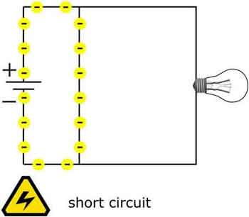
When troubleshooting malfunctioning circuits, one has to know how to test a solid state relay. It’s important to understand what an electrical fault is and recognize its causes and consequences, which can stem from short circuits, ground faults, or overload conditions.
This offers a more controlled environment for evaluating SSR performance. Here are some common offline testing procedures:
Visual Inspection: A basic yet crucial step is to visually inspect the SSR for any signs of physical damage, such as burns, cracks, or discoloration on the housing. Additionally, checking for loose connections or corrosion on terminals is essential.
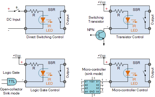
Input LED Diode: Using the multimeter’s diode mode, check the SSR’s input terminals. The forward voltage drop across the internal opto-isolator LED should fall within 1.0–1.5?V DC range. No reading could indicate a failed input circuit.
Control Signal Functionality: This inspection verifies the SSR's response to the control signal. A DC power supply can be used to provide a voltage within the specified control signal range. If the SSR is operational, applying the control signal should activate the output circuit as expected.
Load Current: With the SSR isolated from the load, a controllable current source can simulate the load current. By gradually increasing the current and monitoring the voltage drop across the SSR, its ability to handle the intended load can be assessed. It's important to ensure the current doesn't exceed the SSR's rated capacity.
On-Resistance Measurement: With the SSR turned "on" under load, use a low-resistance meter to measure the output resistance. Values should be low (typically <1?Ω). Higher resistance may indicate internal contact wear or overheating.
Leakage Current Measurement: A sensitive multimeter can be used to measure the leakage current between the SSR's input and output circuits when it's in the off state. Excessive leakage current can indicate internal degradation within the SSR and may necessitate replacement.
On-Resistance Measurement: The on-resistance of the SSR represents the resistance offered by the switching element when it's conducting. A low-resistance meter can be used to measure this value. The measured on-resistance should be within the manufacturer's specifications for the specific SSR model. An increase in on-resistance can indicate potential wear and tear within the switching element.
This allows for a quick assessment of SSR functionality without system downtime. However, these methods may not be as comprehensive as offline examination. Here are some common online approaches:
Control Signal Verification: Similar to the off-line method, a voltage meter can be used to measure the control signal voltage at the SSR's input terminals while the control system is operational. This verifies that the SSR is receiving the appropriate control signal.
Output Voltage Monitoring: For AC SSRs, a voltmeter can be used to measure the load voltage while the SSR is activated. A similar approach can be used with DC SSRs. In both cases, the measured voltage should be close to the supply voltage, indicating proper conduction through the SSR.
Functional Load Testing: Use a live load (e.g., incandescent lamp) to verify that the SSR properly completes the circuit when control voltage is applied. The absence of a load can lead to misleading results, as some SSRs won’t visibly switch without it.
Pulse and Switching Delay Observation (Advanced): An oscilloscope can help measure switching response time and verify zero-cross behavior (if applicable). This is especially useful for high-speed applications and timing-sensitive circuits.
Temperature Monitoring: Using a non-contact temperature sensor, the SSR's housing temperature can be monitored during operation. An abnormal rise in temperature can be a sign of internal issues within the SSR and may warrant further investigation or replacement.
System Performance Observation: Careful monitoring of the control system's overall performance can provide clues to potential SSR malfunctions. Signs like flickering lights, erratic motor behavior, or unexpected equipment shutdowns may indicate issues with the SSRs controlling those functions.
Stay informed with our FREE Electrical Protection Newsletter — get the latest news, breakthrough technologies, and expert insights, delivered straight to your inbox.
Safety is paramount when testing SSRs, especially when dealing with high voltages or currents. Ensure all equipment is properly grounded and follow standard electrical safety procedures to prevent accidents.
Safety is paramount when testing SSRs, especially during offline testing procedures. Here are some crucial safety practices to follow:
Always refer to the manufacturer's datasheet for specific testing instructions and safety precautions.
Ensure the power supply is disconnected and all capacitors are discharged before handling the SSR.
Use appropriate personal protective equipment (PPE) such as safety glasses and gloves when working with electrical components.
Never exceed the SSR's rated voltage, current, or power handling capabilities during testing.
Be mindful of potential hot surfaces during online testing, especially when using temperature sensors
If any discrepancies are identified during testing, further investigation or replacement of the SSR may be necessary. It's important to consult the manufacturer's recommendations for troubleshooting and replacement procedures.
Regular testing of solid-state relays is vital to ensuring the smooth operation and reliability of control systems. By combining offline and online testing procedures, users can proactively identify potential SSR issues and prevent costly downtime. Understanding the appropriate testing methods and safety precautions is crucial for maintaining optimal performance and ensuring the safe operation of SSRs within various applications.
Explore 50+ live, expert-led electrical training courses –