Overcurrent Protection Device Explained
Protective Relay Training - Basic
Our customized live online or in‑person group training can be delivered to your staff at your location.
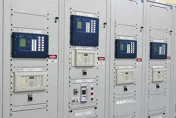
- Live Online
- 12 hours Instructor-led
- Group Training Available
Download Our OSHA 3875 Fact Sheet – Electrical PPE for Power Industry Workers
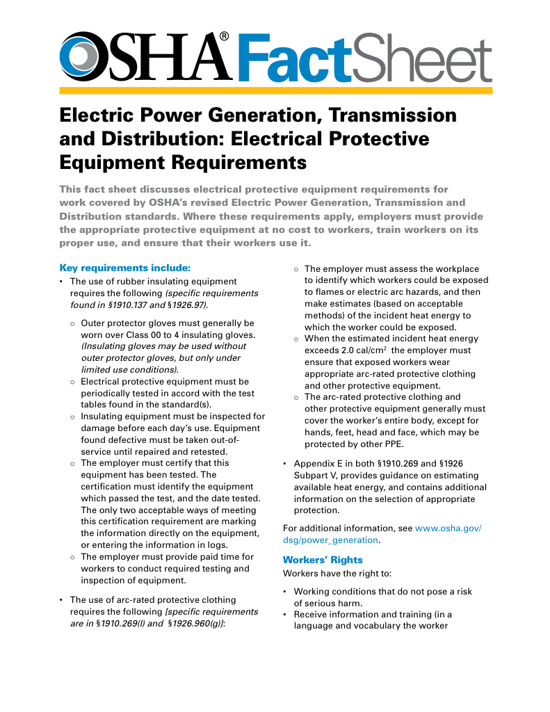
- Follow rules for rubber gloves, arc-rated PPE, and inspection procedures
- Learn employer obligations for testing, certification, and training
- Protect workers from arc flash and electrical shock injuries
An overcurrent protection device (OCPD) is designed to automatically interrupt electrical flow when excessive current occurs, preventing equipment damage and fire hazards. Common OCPDs include fuses and circuit breakers used in industrial electrical systems.
What is an Overcurrent Protection Device?
An overcurrent protection device (OCPD) is a crucial component of modern electrical systems, ensuring the safety of circuits and equipment by interrupting the flow of electricity in the event of an overcurrent situation. It:
✅ Prevents electrical fires and equipment damage by limiting current flow
✅ Includes fuses, circuit breakers, and protective relays
✅ Essential for safe residential, commercial, and industrial systems
Basic Protection Relay Training
Request a Free Training Quotation
Overcurrent occurs when the current flowing through a circuit exceeds its safe limit, which can result from a short circuit, ground fault, or overload. OCPDs detect these dangerous conditions and either open the circuit or interrupt current flow to protect conductors and equipment. By doing so, they reduce the risk of electrical fires, arc flash hazards, and costly downtime. Understanding the types of overcurrent protection devices is essential for designing systems that comply with OCPD standards, NEC, NFPA, and UL requirements.
Device Types
Overcurrent protection devices provide defence against electrical faults, short circuits, or overloads. Whether safeguarding residential wiring, industrial panels, or utility substations, these devices maintain safe operation by detecting abnormal current levels and triggering interruption before damage occurs.
-
Fuses react instantly to high current and are cost-effective for sensitive equipment.
-
Circuit breakers offer resettable protection, with advanced designs featuring trip curves tailored to various applications.
-
Protective relays coordinate large-scale systems, including switchgear and substations.
-
GFCIs and AFCIs protect residential systems against ground faults and arc faults.
Choosing the right device often means comparing fuse vs circuit breaker coordination. While fuses offer speed and precision, breakers provide reset capability and are easier to maintain in industrial or utility-scale systems. Proper protective relay coordination also ensures safe operation in complex power systems.
Sign Up for Electricity Forum’s Electrical Protection Newsletter
Stay informed with our FREE Electrical Protection Newsletter — get the latest news, breakthrough technologies, and expert insights, delivered straight to your inbox.
Selectivity and Coordination
Selectivity, or protective coordination, ensures that only the device closest to a fault trips, preserving continuity of service. Poor coordination can result in nuisance tripping, causing the shutdown of entire feeders unnecessarily. By matching time-current curves of upstream and downstream devices, engineers ensure selective isolation of faults. Devices such as circuit protection devices are designed to detect faults and isolate affected sections, ensuring safety and reliability.
Poor selectivity can lead to nuisance tripping, where a small downstream fault disables an entire feeder or facility. By properly coordinating the time-current characteristics between devices (such as fuses and circuit breakers), engineers can ensure that only the affected portion of a circuit is de-energized.
Key Concepts:
-
Upstream vs. downstream devices: The upstream device (e.g., main breaker) should have a delayed response compared to downstream breakers.
-
Zone Selective Interlocking (ZSI): Some systems utilize digital communication between breakers to dynamically adjust trip times, thereby improving selectivity.
-
NEC 240.12 recommends documented coordination studies for essential systems.
Simplified OCPD Comparison Table
| Device Type | Function | Response Time | Typical Use |
|---|---|---|---|
| Fuse | Melts to open circuit | Instant to fast | Residential panels, small electronics |
| Circuit Breaker | Trips to stop current flow | Fast (resettable) | Homes, offices, distribution boards |
| Thermal Breaker | Detects overload via heat | Slower (delayed trip) | Motors, lighting, HVAC systems |
| Protective Relay | Sends a trip signal when a fault is detected | Programmable | Substations, industrial switchgear |
| GFCI | Trips on ground faults | <1 second | Bathrooms, kitchens, outdoor outlets |
| AFCI | Detects dangerous arc faults | <1 second | Bedrooms, wall wiring, new construction |
Time-Current Curves
A time-current curve (TCC) graphically represents the relationship between the magnitude of current and the trip time for an overcurrent protection device. It allows engineers to compare the performance of various devices to ensure selective operation.
Curve Characteristics:
-
X-axis: Multiple of rated current (e.g., 1x to 100x)
-
Y-axis: Time to trip (milliseconds to seconds)
-
Steep slopes: Fast-acting fuses
-
Flat slopes: Inverse-time breakers with delays
Using these curves, designers can overlay devices to ensure that downstream protection activates before upstream protection, vital for selectivity and compliance.
Example:
-
A 20A branch breaker may trip in 0.1s at 100A, while a 100A main breaker delays for 1s at the same current level.
Applicable Standards and Codes
Overcurrent protection devices are governed by multiple electrical safety codes and international standards, ensuring devices operate safely and reliably:
Key Standards:
-
NEC Article 240: Overcurrent protection for conductors and short-circuit ratings.
-
NFPA 70E: Reduces arc flash hazards through properly rated OCPDs.
-
UL 489: Testing for molded case circuit breakers.
-
IEC 60269 / IEC 60947: Global fuse and breaker standards.
-
ANSI C37: Protective relay and breaker operation.
Compliance with these standards ensures that the selected devices:
-
Are appropriately rated for interrupt capacity
-
Match the load characteristics
-
Conform to local safety regulations
Real-World Scenarios: How OCPDs Respond
-
Industrial motor overload: A thermal breaker protects conveyors, HVAC systems, and pumps from overheating.
-
Residential short circuit: A fuse blows instantly in a lighting circuit, preventing the insulation from melting.
-
Arc fault in outlet: AFCI disconnects sparking outlets to prevent fire.
-
Utility feeder fault: The relay detects a ground fault and trips only the affected feeder breaker, thereby preserving system reliability.
Modern systems benefit from protective relays and multifunction relays, which offer fast and intelligent responses to electrical faults.
Frequently Asked Questions
What is the interrupting capacity of an OCPD?
Interrupting rating defines the maximum short-circuit current the device can safely withstand. Selecting a device with an insufficient rating can result in catastrophic failure. Understanding the role of current-limiting fuses can help reduce the energy loss during a short-circuit event.
How do OCPDs reduce arc flash risk?
By clearing faults quickly and using current-limiting designs, OCPDs minimize incident energy. Proper relay coordination and arc-flash studies further reduce hazards. Learning about different types of short circuit faults in power systems helps ensure that your protective strategy matches your application’s fault characteristics.
What is selective coordination, and why is it required by NEC?
Selective coordination ensures only the affected device trips. NEC 240.12 mandates coordination studies for critical systems, such as hospitals and data centers, to guarantee service continuity. Selecting the correct circuit breaker type is crucial for effective short-circuit fault mitigation, particularly in industrial and high-load environments.
What are the different types of overcurrent protection devices?
Fuses, breakers, relays, AFCIs, and GFCIs provide tailored protection across residential, industrial, and utility systems.
How do you select the appropriate OCPD?
Selection depends on load type, interrupting rating, short-circuit withstand requirements, and compliance with NEC guidelines. Current-limiting fuses and relays are essential for high-energy fault environments.
Electricity Today T&D Magazine Subscribe for FREE

- Timely insights from industry experts
- Practical solutions T&D engineers
- Free access to every issue
What is the key difference between fuses and circuit breakers
Fuses must be replaced after operation, but they offer speed and precision. Breakers, on the other hand, are resettable and more practical for large installations. Fuse vs circuit breaker coordination is a critical design step.
A thorough short circuit analysis, combined with regular system testing and review of fault current ratings, is essential. Consulting with an electrical engineer ensures your protective devices are correctly rated and coordinated for your specific load and environment.
Related Articles


