What is an Electrical Fault?

By R.W. Hurst, Editor
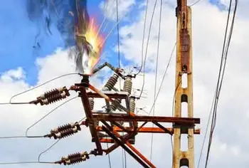

what is an electrical fault

An electrical fault occurs when a system or piece of equipment departs from its normal operating state, resulting in abnormal current flow. This can result in overheating, equipment damage, or safety risks. Protective devices isolate faults to preserve safety and reliability.


What is an Electrical Fault?

An electrical fault is an abnormal condition in a power system or equipment. It happens when the current flowing through a circuit is partially or completely interrupted.

✅ Short circuits, ground faults, and overloads are common types

✅ Protective devices mitigate hazards and equipment damage

✅ Fault detection ensures system safety and reliability


Electrical faults can occur for various reasons, including equipment failure, environmental conditions, and human error. Some common causes of electrical faults include faulty wiring, damaged insulation, overloaded circuits, lightning strikes, power surges, and voltage fluctuations. 

  • Equipment issues: faulty wiring, broken insulation, overloaded circuits

  • Environmental conditions: moisture, lightning, dust, or tree contact

  • Human error: poor installation, neglect, or unsafe work practices

The most common fault categories include open-circuit faults, short-circuit faults, and ground faults. An open circuit fault occurs when a break in the circuit prevents current from flowing. A short circuit occurs when an unintended connection between two points allows an excessive amount of current to flow. A ground fault occurs when an unintended connection between the electrical circuit and the ground creates a shock hazard. Faults often relate to excessive current flow, which can be better understood through Ohm’s Law and its role in determining resistance, voltage, and current relationships.

A balanced fault is a condition in which all three phases of a three-phase system are shorted to ground or to each other. In this type of fault, the system remains balanced, and the fault current is limited. Understanding basic electricity is essential to grasp how faults disrupt the normal flow of current in a circuit.


Classifications of Electrical Faults

Electrical faults can be categorized into several groups to help engineers understand their causes and plan effective protective measures.

Transient vs. Permanent Faults: Transient faults, such as those caused by a lightning strike or temporary contact with a tree branch, clear on their own once the source is removed. Permanent faults, on the other hand, require repair before normal operation can resume, such as when insulation fails or a conductor breaks.

Symmetric vs. Asymmetric Faults: A symmetric fault affects all three phases of a system equally, and although rare, it can cause severe damage due to the high fault currents it generates. Asymmetric faults are far more common, involving one or two phases, and they create an unbalanced condition in the system.

Internal vs. External Faults: Internal faults occur within equipment, such as transformers, generators, or motors, often due to insulation breakdown or winding damage. External faults originate outside the equipment, caused by conditions such as storm damage, contact with foreign objects, or human error.


Types of Electrical Faults in Power Systems

A line-to-ground fault occurs when one of the conductors in a circuit comes in contact with the ground. This can happen due to faulty insulation, damaged equipment, or environmental conditions. A common example is a lightning strike creating a transient line-to-ground fault that trips breakers on a distribution system.

Other major types include:

  • Line-to-ground: conductor touches ground, causing shock risk

  • Open circuit: broken wires or components stop current flow

  • Phase fault: phases contact each other or ground

  • Short circuit: an unintended connection allows excessive current

  • Single-phase: limited to one phase, but still damaging

  • Arc fault: current jumps an air gap, creating sparks and fire risk

  • Balanced vs unbalanced: equal current in phases vs uneven distribution

Rodents chewing through insulation in attics or utility spaces often cause arc faults, showing how even small intrusions can lead to dangerous electrical events. When discussing ground faults and protective systems, it’s useful to revisit the conductor definition, since conductors are the pathways through which electrical energy travels and where faults typically occur.


Electrical Fault Protection Systems and Safety Devices

A circuit breaker is a device that automatically interrupts the flow of current in a circuit when it detects a fault. It is an essential safety device that helps prevent fires and other hazards.

When a circuit is interrupted, the flow of current in the circuit is stopped. This can happen for various reasons, including a circuit fault, a switch or breaker opening, or other similar issues.

In an electric power system, faults can cause significant damage to system equipment and result in power outages. Power system equipment includes transformers, generators, and other devices that are used to generate, transmit, and distribute power.

  • Circuit breakers: interrupt current when faults are detected

  • Relays: monitor and signal breakers to operate

  • Fuses: provide overcurrent protection in smaller systems

  • GFCIs: stop leakage current to ground instantly

  • AFCIs: detect arc faults to prevent electrical fires

Modern protective relay schemes, such as distance relays, differential relays, and overcurrent relays, provide precise and selective fault detection in high-voltage power systems. Engineers also use fault current analysis and time–current coordination studies to ensure that devices operate in the right order, isolating only the affected portion of the network.

Voltage drop refers to the reduction in voltage that occurs when current flows through a circuit. Various factors, including the resistance of the circuit components and the distance between the power source and the load, can cause voltage drops. Many fault events lead to abnormal heating or circuit interruption, highlighting the importance of electrical resistance and how it affects system reliability.


Signs, Hazards & Prevention

Electrical hazards refer to any situation or condition that poses a risk of injury or damage. Various factors, including faulty equipment, damaged insulation, or human error, can cause hazards. Faulty wiring refers to any damaged, frayed, or deteriorated wiring. Faulty wiring can cause faults and create safety hazards for people nearby.

The signs of a fault can vary depending on the type of fault and its location. However, some common signs include flickering lights, frequent circuit breaker trips, burning odours, and overheating equipment.

  • Warning signs: flickering lights, breaker trips, overheating, burning odours

  • Safety hazards: electric shock, fire, equipment damage

  • Prevention steps: inspections, correct equipment sizing, avoiding overloads, and code compliance

It is crucial to follow proper safety practices to prevent faults from occurring. This includes regular maintenance and inspection of equipment, using the correct type and size of electrical components, and avoiding overloading circuits. It is also essential to use circuit breakers, GFCIs, and other protective devices as required by code. For a broader perspective, exploring the dangers of electricity helps explain why protective devices and fault detection are so critical for both personal safety and equipment protection.


Frequently Asked Questions
 

How do faults occur?

Faults can occur for various reasons, including equipment failure, environmental conditions, and human error. Some common causes of faults include faulty wiring, damaged insulation, overloaded circuits, lightning strikes, power surges, and voltage fluctuations.


What are the most common types of faults?

The most common types of faults include open-circuit faults, short-circuit faults, and ground faults.


What are the signs of a fault?

The signs of a fault can vary depending on the type of fault and its location. However, some common signs of an electrical fault include flickering lights, circuit breakers tripping frequently, burning smells, and overheating equipment.


How can you prevent faults from occurring?

It is crucial to follow proper safety practices to prevent faults from occurring. This includes regular maintenance and inspection of equipment, using the correct type and size of electrical components, and avoiding overloading circuits. It is also essential to use circuit breakers and other protective devices.


Related Articles


Related News

What is an Electrical Fault?

An electrical fault occurs when a system or piece of equipment departs from its normal operating state, resulting in abnormal current flow. This can result in overheating, equipment damage, or safety risks. Protective devices isolate faults to preserve safety and reliability.


What is an Electrical Fault?

An electrical fault is an abnormal condition in a power system or equipment. It happens when the current flowing through a circuit is partially or completely interrupted.

✅ Short circuits, ground faults, and overloads are common types

✅ Protective devices mitigate hazards and equipment damage

✅ Fault detection ensures system safety and reliability


Electrical faults can occur for various reasons, including equipment failure, environmental conditions, and human error. Some common causes of electrical faults include faulty wiring, damaged insulation, overloaded circuits, lightning strikes, power surges, and voltage fluctuations. 

  • Equipment issues: faulty wiring, broken insulation, overloaded circuits

  • Environmental conditions: moisture, lightning, dust, or tree contact

  • Human error: poor installation, neglect, or unsafe work practices

The most common fault categories include open-circuit faults, short-circuit faults, and ground faults. An open circuit fault occurs when a break in the circuit prevents current from flowing. A short circuit occurs when an unintended connection between two points allows an excessive amount of current to flow. A ground fault occurs when an unintended connection between the electrical circuit and the ground creates a shock hazard. Faults often relate to excessive current flow, which can be better understood through Ohm’s Law and its role in determining resistance, voltage, and current relationships.

A balanced fault is a condition in which all three phases of a three-phase system are shorted to ground or to each other. In this type of fault, the system remains balanced, and the fault current is limited. Understanding basic electricity is essential to grasp how faults disrupt the normal flow of current in a circuit.


Classifications of Electrical Faults

Electrical faults can be categorized into several groups to help engineers understand their causes and plan effective protective measures.

Transient vs. Permanent Faults: Transient faults, such as those caused by a lightning strike or temporary contact with a tree branch, clear on their own once the source is removed. Permanent faults, on the other hand, require repair before normal operation can resume, such as when insulation fails or a conductor breaks.

Symmetric vs. Asymmetric Faults: A symmetric fault affects all three phases of a system equally, and although rare, it can cause severe damage due to the high fault currents it generates. Asymmetric faults are far more common, involving one or two phases, and they create an unbalanced condition in the system.

Internal vs. External Faults: Internal faults occur within equipment, such as transformers, generators, or motors, often due to insulation breakdown or winding damage. External faults originate outside the equipment, caused by conditions such as storm damage, contact with foreign objects, or human error.


Types of Electrical Faults in Power Systems

A line-to-ground fault occurs when one of the conductors in a circuit comes in contact with the ground. This can happen due to faulty insulation, damaged equipment, or environmental conditions. A common example is a lightning strike creating a transient line-to-ground fault that trips breakers on a distribution system.

Other major types include:

  • Line-to-ground: conductor touches ground, causing shock risk

  • Open circuit: broken wires or components stop current flow

  • Phase fault: phases contact each other or ground

  • Short circuit: an unintended connection allows excessive current

  • Single-phase: limited to one phase, but still damaging

  • Arc fault: current jumps an air gap, creating sparks and fire risk

  • Balanced vs unbalanced: equal current in phases vs uneven distribution

Rodents chewing through insulation in attics or utility spaces often cause arc faults, showing how even small intrusions can lead to dangerous electrical events. When discussing ground faults and protective systems, it’s useful to revisit the conductor definition, since conductors are the pathways through which electrical energy travels and where faults typically occur.


Electrical Fault Protection Systems and Safety Devices

A circuit breaker is a device that automatically interrupts the flow of current in a circuit when it detects a fault. It is an essential safety device that helps prevent fires and other hazards.

When a circuit is interrupted, the flow of current in the circuit is stopped. This can happen for various reasons, including a circuit fault, a switch or breaker opening, or other similar issues.

In an electric power system, faults can cause significant damage to system equipment and result in power outages. Power system equipment includes transformers, generators, and other devices that are used to generate, transmit, and distribute power.

  • Circuit breakers: interrupt current when faults are detected

  • Relays: monitor and signal breakers to operate

  • Fuses: provide overcurrent protection in smaller systems

  • GFCIs: stop leakage current to ground instantly

  • AFCIs: detect arc faults to prevent electrical fires

Modern protective relay schemes, such as distance relays, differential relays, and overcurrent relays, provide precise and selective fault detection in high-voltage power systems. Engineers also use fault current analysis and time–current coordination studies to ensure that devices operate in the right order, isolating only the affected portion of the network.

Voltage drop refers to the reduction in voltage that occurs when current flows through a circuit. Various factors, including the resistance of the circuit components and the distance between the power source and the load, can cause voltage drops. Many fault events lead to abnormal heating or circuit interruption, highlighting the importance of electrical resistance and how it affects system reliability.


Signs, Hazards & Prevention

Electrical hazards refer to any situation or condition that poses a risk of injury or damage. Various factors, including faulty equipment, damaged insulation, or human error, can cause hazards. Faulty wiring refers to any damaged, frayed, or deteriorated wiring. Faulty wiring can cause faults and create safety hazards for people nearby.

The signs of a fault can vary depending on the type of fault and its location. However, some common signs include flickering lights, frequent circuit breaker trips, burning odours, and overheating equipment.

  • Warning signs: flickering lights, breaker trips, overheating, burning odours

  • Safety hazards: electric shock, fire, equipment damage

  • Prevention steps: inspections, correct equipment sizing, avoiding overloads, and code compliance

It is crucial to follow proper safety practices to prevent faults from occurring. This includes regular maintenance and inspection of equipment, using the correct type and size of electrical components, and avoiding overloading circuits. It is also essential to use circuit breakers, GFCIs, and other protective devices as required by code. For a broader perspective, exploring the dangers of electricity helps explain why protective devices and fault detection are so critical for both personal safety and equipment protection.


Frequently Asked Questions
 

How do faults occur?

Faults can occur for various reasons, including equipment failure, environmental conditions, and human error. Some common causes of faults include faulty wiring, damaged insulation, overloaded circuits, lightning strikes, power surges, and voltage fluctuations.


What are the most common types of faults?

The most common types of faults include open-circuit faults, short-circuit faults, and ground faults.


What are the signs of a fault?

The signs of a fault can vary depending on the type of fault and its location. However, some common signs of an electrical fault include flickering lights, circuit breakers tripping frequently, burning smells, and overheating equipment.


How can you prevent faults from occurring?

It is crucial to follow proper safety practices to prevent faults from occurring. This includes regular maintenance and inspection of equipment, using the correct type and size of electrical components, and avoiding overloading circuits. It is also essential to use circuit breakers and other protective devices.


Related Articles


View more

What is a Capacitor?

A capacitor is an electrical component that stores and releases energy in a circuit. It consists of two conductive plates separated by an insulator and is commonly used for filtering, power conditioning, and energy storage in electronic and electrical systems.


What is a Capacitor?

A capacitor is a key component in electronics and power systems. It temporarily stores electrical energy and is widely used in both AC and DC circuits.

✅ Stores and discharges electrical energy efficiently

✅ Used in filtering, timing, and power factor correction

✅ Found in electronics, motors, and power supplies

It is designed for energy storage and can store electric charges, which can be released when needed. In this article, we will delve into the fundamentals of capacitors, including their functions, types, and applications. To better understand how capacitors support overall system performance, explore our Power Quality overview covering the fundamentals of voltage stability and energy flow.

Power Quality Analysis Training

Power Factor Training

Request a Free Power Quality Training Quotation

A capacitor consists of two metallic plates separated by an insulating material known as the dielectric. The dielectric can be made from various materials, such as mica, paper, or ceramic. When voltage is applied across the plates, positive charges accumulate on one plate, while negative charges accumulate on the opposite plate. The amount of capacitor charge that can be stored depends on several factors, including plate area, plate separation, dielectric material, and voltage ratings. Capacitors are often used in capacitor banks to improve power factor and reduce energy losses in electrical systems.

How does a capacitor work? The primary function of a capacitor in an electronic circuit is to store electrical energy. Capacitors can be used for various purposes, such as filtering, timing, and coupling or decoupling signals. In addition, they play a crucial role in power supplies, ensuring that the output voltage remains stable even when there are fluctuations in the input voltage. Learn how capacitive loads influence circuit behavior and why they require precise capacitor selection for optimal performance.

A capacitor stores energy through the electrostatic field created between its plates. The stored energy can be calculated using the formula E = 0.5 * C * V^2, where E is the stored energy, C is the capacitance, and V is the voltage across the capacitor. Capacitance, measured in Farads, is a measure of a capacitor's ability to store charge. The capacitor voltage rating is crucial for ensuring safe operation and preventing dielectric breakdown during voltage spikes.

So, when I am asked what is a capacitor? I tell readers about several types of capacitors, each with unique applications. Common types include ceramic, electrolytic, film, and tantalum capacitors. Ceramic capacitors are widely used due to their low cost and small size. They are ideal for high-frequency applications and decoupling in power supply circuits. On the other hand, Electrolytic capacitors are popular for their high capacitance values and are commonly used in filtering and energy storage applications. Capacitors play a crucial role in power factor correction, enabling industrial systems to reduce demand charges and enhance energy efficiency.

Dielectric materials used in capacitors can be organic (such as paper) or inorganic (such as ceramic). The choice of dielectric material depends on factors like the desired capacitance value, voltage rating, and operating temperature range. Additionally, different dielectric materials exhibit varying properties, making them suitable for specific applications. For a deeper understanding of energy relationships, see how apparent power differs from real and reactive power in systems using capacitors.

A capacitor can be classified as polarized or non-polarized based on the presence or absence of polarity. Polarized capacitors, like electrolytic capacitors, have a positive and a negative terminal and must be connected correctly in a circuit to function properly. Non-polarized capacitors, like ceramic capacitors, do not have a specific polarity and can be connected in any orientation.

A Capacitor behaves differently in AC and DC voltage circuits. In DC circuits, once a capacitor is charged, it blocks the flow of current, essentially acting as an open circuit. However, in ac voltage circuits, capacitors allow the flow of alternating current. This phenomenon is known as displacement current, which occurs due to the continuous charging and discharging of charges.

So, what is a capacitor? Understanding what a capacitor is and how it works is essential for anyone interested in electronics. The Capacitor plays a vital role in a wide range of applications, from energy storage and filtering to signal coupling and decoupling. Understanding the various types of capacitors and their specific applications enables you to make informed decisions when designing or troubleshooting electronic circuits. Explore how an automatic power factor controller dynamically adjusts capacitor usage to maintain an efficient power factor in real-time.


Related Articles


View more

Capacitance in Parallel Explained

Capacitance in parallel occurs when capacitors are connected side by side, and their values add together. This increases total capacitance, ensures stable voltage, supports efficient charge distribution, and is essential in electronics, energy storage, and reliable circuit design.


What is Capacitance in Parallel?

Capacitance in parallel occurs when capacitors are connected across the same two points in a circuit, causing their capacitance to add up:

✅ Increases total capacitance by summing all capacitor values

✅ Improves energy storage and voltage regulation in circuits

✅ Common in AC and DC applications for a consistent charge supply

To learn the fundamentals, see what is capacitance, which explains how capacitors store charge, the role of farads, and why this property is essential in circuits and energy storage.


Understanding Parallel Capacitor Behavior

When capacitors are connected in parallel, the effective plate area increases, and the total capacitance is the sum of the individual capacitances. Figure 1 shows a simplified parallel circuit. The total charging current from the source divides at the junction of the parallel branches. To fully understand how capacitors behave in parallel, it helps to revisit the basics of what is a capacitor and how capacitance works in circuits. 


Fig. 1 - Simplified parallel circuit.


There is a separate charging current through each branch, allowing a different charge to be stored by each capacitor. Using Kirchhoff’s current law, the sum of all the charging currents is then equal to the total current. The sum of the charges (Q) on the capacitors is equal to the total charge on the capacitors. The voltages (E) across all of the parallel branches are equal. With all of this in mind, a general equation for capacitors in parallel can be determined as:

QT = Q1 + Q2 + Q3

Because Q = CE: CTET = C1E1 + C2E2 + C3E3

Voltages can be factored out because:

ET = E1 + E2 + E3

Leaving us with the equation for capacitors in parallel:

CT = C1 + C2 + C3

Consider the following example:

If C1 = 330μF, C2 = 220μF

Then CT = 330μF + 220μF = 550μF

To calculate the total capacitance in a parallel combination, you simply add the values of the individual capacitors together. This method is straightforward and differs from series connections, where the reciprocal of each capacitor must be used. The total increases with the number of capacitors added in parallel, making this configuration ideal for applications that require higher capacitance. When designing circuits, understanding how a parallel combination enhances energy storage compared to a series connection is crucial for selecting the optimal number of capacitors to achieve the desired performance. For a detailed breakdown of how capacitance is measured, check out the unit of capacitance to understand farads and their practical conversions.

Since voltage remains constant across parallel capacitors, a firm grasp of what is voltage and its behavior in different configurations is essential.


Capacitance in Alternating Current

If a source of alternating current is substituted for the battery, the capacitor acts quite differently than it does with direct current. When an alternating current is applied in the circuit, the charge on the plates constantly changes. [Figure 2] This means that electricity must flow first from Y clockwise around to X, then from X counterclockwise around to Y, then from Y clockwise around to X, and so on. Although no current flows through the insulator between the plates of the capacitor, it constantly flows in the remainder of the circuit between X and Y. In a circuit in which there is only capacitance, current leads the applied voltage, as contrasted with a circuit in which there is inductance, where the current lags the voltage. Capacitors in AC circuits are deeply influenced by alternating current, where the current leads the voltage due to capacitive reactance.


Fig. 2 - Capacitor in an AC circuit.

The parallel connection rule CT = C1 + C2 + C3 reflects the broader principles of resistances in parallel, though capacitance behaves in an additive way instead of being reciprocal.


Capacitive Reactance Xc

The effectiveness of a capacitor in allowing an AC flow to pass depends upon the capacitance of the circuit and the applied frequency. To what degree a capacitor allows an AC flow to pass depends largely upon the capacitive value of the capacitor, given in farads (F). The greater the capacitance, the greater the number of electrons, measured in coulombs, necessary to bring the capacitor to a fully charged state. Once the capacitor approaches or actually reaches a fully charged condition, the polarity of the capacitor will oppose the polarity of the applied voltage, essentially acting then as an open circuit.

To further illustrate this characteristic and how it manifests itself in an AC circuit, consider the following:
If a capacitor has a large capacitive value, a high-frequency current can alternate through it without the capacitor ever reaching a full charge. In this case, the capacitor may offer very little resistance to current.

However, the smaller the capacitance, the fewer electrons are required to bring it up to a full charge, and it is more likely that the capacitor will build up enough of an opposing charge to present significant resistance, possibly behaving like an open circuit. Understanding Kirchhoff’s Law helps explain how current divides among parallel capacitors and supports accurate calculations.


Comparison With Series Capacitance

Understanding the difference between series and parallel capacitance is critical for circuit design:

Configuration Total Capacitance Voltage Behavior Current Behavior
Parallel Adds directly: CT = C1 + C2 + ... Same across all components Divides among branches
Series Inverse sum: 1/CT = 1/C1 + 1/C2 + ... Divides across components Same through all components
  • Parallel is best when you want more capacitance and voltage stability.

  • Series is used when you need a lower total capacitance or to increase voltage tolerance.

To explore how capacitors behave when connected end-to-end, visit capacitance in series, which explains the reciprocal formula and voltage behavior.


Practical Design Considerations

  • Voltage Rating: In parallel, all capacitors share the same voltage. The lowest voltage rating among capacitors determines the safe operating voltage of the group.

  • Physical Size: Adding more capacitors increases board space. Designers must balance performance with space constraints.

  • Energy Storage: Parallel configurations store more energy, making them ideal for power supplies, smoothing circuits, and buffering in audio and RF systems.

Real-world circuit design also requires familiarity with types of capacitors, as their materials and tolerances affect total capacitance and performance.


Real-World Applications of Parallel Capacitors

  • Power Supply Smoothing: Bulk capacitors in parallel stabilize the DC output.

  • Decoupling Noise: Small-value capacitors placed in parallel with larger ones eliminate high-frequency interference.

  • Tuning Circuits: In radio circuits, variable capacitors, when used in parallel with fixed ones, help tune specific frequencies.

For a broader context, you can explore how electrical resistance and reactive power relate to capacitive elements in AC power systems.


Related Articles


View more

Electricity How it Works

Electricity How It Works explains electron flow, voltage, current, resistance, and power in circuits, from generation to distribution, covering AC/DC systems, Ohm's law, conductors, semiconductors, transformers, and energy conversion efficiency and safety.


What Is Electricity How It Works?

Explains electron flow, voltage, current, resistance, and power conversion in AC/DC circuits and key components.

✅ Voltage drives current through resistance per Ohm's law (V=IR).

✅ AC/DC systems distribute power via transformers and rectifiers.

✅ Conductors, semiconductors, capacitors, inductors shape circuits.


Electricity How It Works - This is a very common question. It can best be explained by stating this way: Single-phase electricity is what you have in your house. You generally talk about household electrical service as single-phase, 120-volt AC service. If you use an oscilloscope and look at the power found at a normal wall-plate outlet in your house, what you will find is that the power at the wall plate looks like a sine wave, and that wave oscillates between -170 volts and 170 volts (the peaks are indeed at 170 volts; it is the effective (rms) voltage that is 120 volts). The rate of oscillation for the sine wave is 60 cycles per second. Oscillating power like this is generally referred to as AC, or alternating current. The alternative to AC is DC, or direct current. Batteries produce DC: A steady stream of electrons flows in one direction only, from the negative to the positive terminal of the battery.

For a refresher on fundamentals, the overview at what is electricity explains charge, current, and voltage in practical terms.

AC has at least three advantages over DC in an electricity power distribution grid:

1. Large electricity generators happen to generate AC naturally, so conversion to DC would involve an extra step.
2. Electrical Transformers must have alternating current to operate, and we will see that the power distribution grid depends on transformers. 
3. It is easy to convert AC to DC but expensive to convert DC to AC, so if you were going to pick one or the other AC would be the better choice.

To connect these advantages to real-world practice, the primer on basic electricity clarifies AC versus DC behavior, impedance, and safety basics.

The electricity generating plant, therefore, produces AC. For a deeper look at how rotating machines induce AC, see the overview of electricity generators and their role in utility-scale plants.


Electricity How it Works in The Power Plant: Three-phase Power

If you want a quick walkthrough from generation to loads, this guide on how electricity works ties the concepts together before we examine three-phase specifics.

The power plant produces three different phases of AC power simultaneously, and the three phases are offset 120 degrees from each other. There are four wires coming out of every power plant: the three phases plus a neutral or ground common to all three. If you were to look at the three phases on a graph, they would look like this relative to ground:

A concise visual explainer on three-phase electricity shows how 120-degree phase offsets create balanced currents in feeders.

Electricity How It Works - There is nothing magical about three-phase power. It is simply three single phases synchronized and offset by 120 degrees. For wiring diagrams and common configurations, explore 3-phase power examples used across industrial facilities.

Why three phases? Why not one or two or four? In 1-phase and 2-phase electricity, there are 120 moments per second when a sine wave is crossing zero volts. In 3-phase power, at any given moment one of the three phases is nearing a peak. High-power 3-phase motors (used in industrial applications) and things like 3-phase welding equipment therefore have even power output. Four phases would not significantly improve things but would add a fourth wire, so 3-phase is the natural settling point.

Practical comparisons of motor torque ripple and line loading in 3-phase electricity help illustrate why three conductors strike the best balance.

And what about this "ground," as mentioned above? The power company essentially uses the earth as one of the wires in the electricity system. The earth is a pretty good conductor and it is huge, so it makes a good return path for electrons. (Car manufacturers do something similar; they use the metal body of the car as one of the wires in the car's electrical system and attach the negative pole of the battery to the car's body.) "Ground" in the power distribution grid is literally "the ground" that's all around you when you are walking outside. It is the dirt, rocks, groundwater, etc., of the earth.


Related Articles

View more

What is Considered High Voltage? HV Applications Explained

What is considered high voltage? Per IEC/IEEE, voltages above 1 kV AC or 1.5 kV DC; linked to insulation coordination, arc-flash risk, transmission lines, substations, switchgear ratings, clearance/creepage distances, and dielectric breakdown in power systems.


What Is Considered High Voltage?

Voltages above 1 kV AC or 1.5 kV DC are classed as high voltage per IEC/IEEE in power systems.

✅ IEC/IEEE: >1 kV AC or >1.5 kV DC thresholds

✅ Categories: MV, HV, EHV, UHV in power transmission

✅ Impacts insulation, clearance, arc-flash, switchgear ratings


What is Considered High Voltage?

In the world of electrical engineering, understanding voltage levels is crucial. So you might be asked to define high voltage. But what is considered HV? This article explores the definition, classification, and applications of HV and the safety concerns and precautions that come with it. For foundational context, the concept of voltage underpins how these levels are defined and compared across systems.


According to the International Electrotechnical Commission (IEC), HV is typically defined as any voltage above 1000 volts for alternating current (AC) systems and 1500 volts for direct current (DC) systems. However, the term "HV" can also refer to voltages as low as 50 volts in some safety regulations, depending on the context. For example, the US Occupational Safety and Health Administration (OSHA) defines HV as 600 volts or higher in their safety guidelines. Standards often reference nominal voltage values that guide equipment ratings, insulation clearances, and test criteria in practice.

High voltage systems are essential in electric power transmission and distribution, allowing electricity to be transported over long distances with minimal energy loss. Power lines, transmission lines, and transformers all play a role in the power transmission and distribution process. Transformers are used to step up or down voltage levels, depending on whether the electricity is transported over long distances or distributed to end-users. At the point of use, networks step down to low voltage levels suitable for residential and commercial equipment before final delivery.

Voltage classification is a method for organizing voltages based on their range. There are four primary classifications of voltage levels: low (LV), medium  (MV), HV, and extra HV (EHV). Ultra HV (UHV) is another classification for exceptionally high voltages, typically used in long-distance power transmission projects. In distribution grids, medium voltage tiers bridge the gap between long-distance transmission and local feeders in a coordinated hierarchy.

Insulation is a crucial aspect of HV systems, as it prevents electrical current from leaking and causing short circuits, equipment damage, or even fires. Different types of insulation are used depending on the voltage level and application, such as air, gas, oil, or solid materials like plastics and ceramics. For clarity on terminology used in insulation, dielectric strength, and creepage distances, consult common electricity terms that standardize communication across projects.

HV circuits and equipment, such as transformers and switchgear, are designed to handle higher voltages safely and efficiently. These devices are essential components of power distribution networks and are subject to strict design, manufacturing, and testing standards to ensure reliability and safety.

Working with high voltage circuits presents several electrical hazards, such as electric shock, arc flash, and fires. To mitigate these risks, electrical safety measures must be put in place. Workers with HV equipment must follow safety procedures and use appropriate personal protective equipment (PPE), such as insulated gloves, safety glasses, and arc flash suits. Comprehensive electricity safety programs integrate procedures, labeling, lockout/tagout, and training to reduce incident rates.

So, what is considered high voltage? As mentioned earlier, the IEC defines HV as 1000 volts for AC and 1500 volts for DC. However, some safety regulations might consider voltages as low as 50 or 600 volts as HV.

HV is used in power transmission and distribution to transport electricity efficiently over long distances. Transmission lines, transformers, and other equipment are designed to handle HVs and are integral to power distribution networks.

Safety concerns associated with HV systems include electric shock, arc flash, and fires. Proper safety procedures and protective equipment are necessary to minimize these risks. Understanding the broader dangers of electricity helps contextualize HV-specific risks and informs mitigation strategies.

Transformers handle HV levels by stepping up or stepping down the voltage, allowing for efficient power transmission and distribution. They are designed to withstand HV stresses and are subject to rigorous testing and standards.

Various types of insulation are needed for HV applications, including air, gas, oil, and solid materials like plastics and ceramics. The choice of insulation depends on the level and specific application requirements.

The different classifications of voltage levels include low, medium, HV, extra HV, and ultra HV. These classifications help categorize voltage ranges for various applications and safety standards.

When working with HV equipment, workers should follow safety procedures, use appropriate personal protective equipment, and undergo regular training to stay updated on best practices and safety guidelines.

In conclusion, understanding what is considered HV is crucial for electrical systems' safe and efficient operation. HV plays a vital role in power transmission and distribution, allowing electricity to be transported over long distances with minimal losses. Proper insulation, transformers, and other equipment are designed to handle HV levels and ensure the reliability of the electrical infrastructure. Safety concerns associated with HV systems must be addressed through stringent safety procedures, protective equipment, and worker training. We can maintain a safe and efficient electrical infrastructure by adhering to these guidelines and understanding the importance of classifications.


High, Extra-High and Ultra-HV Classifications

High, extra-high, and ultra-high voltage classifications are categories used to define the levels within electrical systems, particularly in power transmission and distribution networks. These classifications help standardize the design, manufacturing, and operation of electrical equipment and ensure safety and efficiency.


High Voltage (HV):

HV is typically defined as levels between 1000 volts (1 kV) and 100,000 volts (100 kV) for alternating current (AC) systems and between 1500 volts (1.5 kV) and 100,000 volts (100 kV) for direct current (DC) systems. HV systems are commonly used in electric power transmission and distribution networks, substations, and industrial facilities. HV allows for efficient power transmission over long distances while reducing energy loss due to resistance.


Extra-High Voltage (EHV):

Extra-high voltage refers to levels above 100,000 volts (100 kV) and up to 300,000 volts (300 kV) for AC systems and between 100,000 volts (100 kV) and 800,000 volts (800 kV) for DC systems. EHV systems are primarily used for long-distance power transmission, where higher levels reduce energy losses even further. EHV lines and equipment require specialized design, manufacturing, and maintenance to ensure safety, reliability, and efficiency. The use of extra-high voltage is also associated with more stringent safety protocols and larger right-of-way requirements for transmission lines.


Ultra-High Voltage (UHV):

Ultra-high voltage classification is designated for levels above 300,000 volts (300 kV) for AC systems and above 800,000 volts (800 kV) for DC systems. UHV systems are used in large-scale power transmission projects that aim to transmit massive amounts of electricity over very long distances with minimal losses. These projects typically connect major power generation sources, such as hydroelectric or nuclear plants, to far-off load centers or densely populated urban areas. As a result, UHV systems demand the highest level of engineering expertise, rigorous testing, and specialized equipment to ensure their safe and efficient operation.


Related Articles

View more

How Electricity Works

Electricity works by moving electrons through a conductor, creating an electric current. Power stations generate electricity, which travels through wires to homes and businesses. This flow powers devices, lights, and machines, making modern life possible through electric energy and circuits.


Explain How Electricity Works

✅ Electrons move through conductors to create electric current

✅ Power plants convert energy into usable electricity

✅ Electrical systems distribute power to homes, industries, and devices


What Is Electricity and Where Does It Come From?

Electricity energy is as common to us as running water in many areas, especially in industrialized countries. Despite this, there is a great deal of ignorance about this mysterious force and its origin. 

  • The concept of voltage is central to how electricity flows, as it represents the electrical pressure that pushes electrons through a circuit.

  • Understanding alternating current is essential, as it's the form of electricity most commonly delivered to homes and businesses.


Atomic Structure and the Nature of Electric Charge

If you can picture an atom as a sphere, imagine in the nucleus, in the centre, that contains at least one proton and at least one neutron. The proton is positively charged. In orbit around the nucleus is at least one electron, which is negatively charged. The reason they have these opposite charges takes us deep into the realm of quantum physics. We know that the neutron is made up of quarks and the electron is an elementary particle (it is not made up of anything and is a particle in its own right), but the reason why they have opposite charges is a matter beyond my meagre capabilities and, in any case, this area is at the fringes of human knowledge.


Electron Movement and Free Charge in Conductive Materials

Atoms may contain several protons and electrons. This variation is what distinguishes one element from another. Although described as sub-atomic particles, electrons have the properties of both particles and waves when it comes to fields of magnetism in electric circuits. In theory, at least, they could be both at the same time. If you want to know what materials conduct electricity well, see our overview of conductors, which explains how they allow electrons to move freely.

If an atom has no electric charge, i.e. it is neutral, then it contains the same number of protons as electrons. In some materials, most notably metals, the electrons' orbits around the nucleus are quite loose, allowing them to spin away from the atom. When this happens, the atom becomes positively charged because protons are in the majority within the atom. A free electron can join another atom. When this occurs, then the new host atom becomes negatively charged because the electrons are in the majority (assuming the atom was neutral in the first place). Devices like ammeters and multimeters are essential for measuring electrical current and diagnosing circuit performance.


Potential Difference and the Creation of Electric Current

There are many views about the subject. If you ask science experts on YouTube to show how static electricity works, they will report that opposites attract. The greater the difference between the number of electrons and protons, the greater the attraction will be. This is called a potential difference. If we can therefore manage to produce a negative charge at one end of a copper wire and a positive charge at the other end, free electrons would move towards the positive end. As electrons leave those atoms nearest the positive end, they leave behind positively charged atoms. Electrons from neighbouring atoms will be attracted towards these positive atoms, thus creating yet more positive atoms in their wake. This continuing transfer of electrons is called current. The greater the potential difference, or voltage, measured in its unit, the greater the force of the flow of electrons, or current.


Understanding Direct and Alternating Current (DC vs AC)

Electric power can be supplied as direct current (e.g. from car batteries for lighting) or as alternating current (e.g. household mains). To explore the differences between current types, read our guide on the difference between AC and DC, which explains why each type is used in different applications.


How Transformers Adjust Voltage for Power Distribution

Often, an electrical product requires a different voltage from the one supplied by the mains electric power. In these cases, a transformer rating is required. The use of transformers is very common along power lines and in electrical devices. In addition to the step-up transformers that increase voltage, transformers can also reduce voltage. These step-down transformers can be found at utility substations where the very high voltages required to push electrons through long transmission wires are reduced for local consumption.


Related Articles


View more

Sign Up for Electricity Forum’s Newsletter

Stay informed with our FREE Newsletter — get the latest news, breakthrough technologies, and expert insights, delivered straight to your inbox.

Electricity Today T&D Magazine Subscribe for FREE

Stay informed with the latest T&D policies and technologies.
  • Timely insights from industry experts
  • Practical solutions T&D engineers
  • Free access to every issue

Download the 2025 Electrical Training Catalog

Explore 50+ live, expert-led electrical training courses –

  • Interactive
  • Flexible
  • CEU-cerified