Test Equipment
Insulation Resistance Tester For Electrical Maintenance
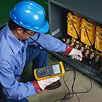
An insulation resistance tester measures the electrical resistance of insulating materials in cables, motors, and equipment. It helps detect insulation breakdown, leakage currents, and moisture intrusion, ensuring electrical safety, equipment longevity, and compliance with industry testing standards.
What is an Insulation Resistance Tester?
An insulation resistance tester is a diagnostic tool used to assess the quality of electrical insulation in systems and components.
✅ Ensures equipment safety by identifying insulation breakdown or degradation
✅ Measures high resistance values in megohms using test voltages
✅ Commonly used in the maintenance of motors, switchgear, and wiring systems
It is a crucial tool in electrical maintenance, used to evaluate the quality of dielectric in various systems. It measures how well the insulation prevents the flow of electrical current, helping to identify potential weaknesses or faults that could lead to equipment failure. Let's explore how these testers work, what features to consider when choosing one, and the safety precautions to follow during testing. Insulation resistance testing is a critical component of a comprehensive electrical testing strategy to verify system reliability and safety.
Frequently Asked Questions
How does an insulation resistance tester work?
It operates by applying a direct current (DC) voltage across the non-conductive layer and measuring the resulting resistance. During the test, a current flows through the insulation material, and the tester measures how much resistance the insulation provides to the flow of electricity. High resistance values indicate a good non-conductive layer, while low resistance values suggest degradation or the presence of moisture. Additionally, the tester can help detect dielectric absorption, which is the ability of the insulation to absorb and release charge over time.
What are the key features to consider?
When selecting a tester, several key features should be evaluated. First, consider the range of test voltages it offers, as different equipment may require varying voltage levels to ensure accurate testing. A wide range of resistance testers can offer voltages from 250V to 5kV or higher, depending on the application. Another important feature is the tester's ability to store and display multiple readings, which is helpful for tracking insulation resistance testing results over time. Additionally, automatic shutoff and overload protection are critical features that enhance both usability and safety.
What types of electrical equipment can be tested?
It can be used on a wide variety of electrical equipment. Motors, transformers, cables, switchgear, and circuit breakers are common examples of equipment tested for quality. Essentially, any component or system that relies on electrical insulation to function safely and effectively can benefit from measuring resistance tests. Regular testing of such equipment can help prevent unplanned outages and equipment failures by identifying insulation issues before they lead to larger problems. When testing motors and rotating equipment, it’s helpful to combine resistance readings with Electric Motor Testing methods to ensure comprehensive analysis.
How do you interpret the results?
Interpreting test results requires understanding the basic relationship between the measured resistance value and the condition of the insulation. Higher resistance values indicate that the non-conductive layer is in good condition and is providing adequate protection. Lower values may indicate contamination, moisture ingress, or aging of the non-conductive layer. Additionally, repeated tests over time enable trend analysis, allowing for the tracking of gradual changes in insulation performance. The dielectric absorption ratio can also be analyzed to provide a more detailed understanding of how the insulation is performing over extended periods.
What safety precautions should be followed?
Safety is paramount when using a tester. Always ensure that the equipment under test is de-energized and properly grounded before commencing the test. Wear the appropriate personal protective equipment (PPE), such as insulated gloves and safety glasses. The tester should also be handled according to the manufacturer’s guidelines to avoid accidents or damage. Lastly, be mindful of the high voltages involved during the test and ensure that no one else is near the equipment being tested.
How Do You Choose the Right One?
Choosing the right tester can be challenging, especially when you're unsure about the specific model, features, or test voltage required. There are six key factors to take into account when selecting the best tester for your needs:
-
What equipment will be tested?
-
What are the voltage requirements for the test?
-
Where will the tests be performed?
-
What insights can this device provide?
-
What is the technician's level of experience?
-
How important is safety in choosing the tool?
Insights from an Insulation Resistance Test
Insulation resistance testing provides a qualitative assessment of the condition of the conductor and the internal resistive medium of various electrical equipment. To begin the test, a DC voltage is applied to the conductor or equipment. This causes a current to flow from the test device into the conductor, charging the insulation. Initially, this current is referred to as a capacitive charging current, and it can be observed on the tester's display.
Initially, the meter will display a lower resistance value as the resistive medium begins to store charge. As more current flows, the reading will show a lower megohm value, indicating how much charge the insulation is holding. If the insulation quality is good, the reading will stabilize at a higher megohm value as the insulation becomes fully charged.
The next type of current is absorption, or polarization, current, which depends on factors such as contamination. For instance, if moisture is present, the absorption current will be higher, resulting in a lower resistance reading. This current takes longer to build compared to the capacitive charging current, so short testing periods may not fully reveal the presence of contaminants.
Lastly, leakage current flows through degraded non-conductive material and into nearby metal components. This current is typically the focus of an insulation resistance test, but for thorough maintenance and troubleshooting, absorption or polarization current should also be evaluated. Some advanced testers are capable of running tests that consider all currents to provide a more complete analysis.
An insulation resistance tester is a vital tool for evaluating the condition of electrical systems. By applying controlled voltages and measuring the resulting resistance, these testers help detect potential non-conductive material failures before they lead to serious issues. Understanding how to operate the tester, selecting the appropriate model, and interpreting test results are crucial for maintaining reliable electrical systems. Always follow safety protocols to ensure a successful and safe testing process. As part of any effective maintenance plan, What is Preventive Maintenance explains how regular testing can extend the life of your electrical systems.
Related Articles
Download Our FREE Test Equipment Handbook

Electrical Testing Maintenance Handbook, Vol. 8
Part of the popular testing and measurement series of handbooks, Volume 8 further examines the crucial elements of proper maintenance and testing techniques essential to minimizing risk and liability.
The Electrical Testing and Maintenance Handbook, Vol. 8 provides a comprehensive resource for professionals involved in the testing, inspection, and maintenance of electrical systems and equipment. Whether you're an electrical engineer, technician, or facility manager, this handbook offers valuable insights into the best practices, methods, and tools required to ensure that your electrical systems are operating at peak efficiency, are compliant with industry standards, and are safe for use.
In this edition, we cover a wide array of topics related to the maintenance and testing of various electrical components, including circuit breakers, transformers, switchgear, relays, and protective devices. The handbook delves into the different testing techniques used to assess equipment performance and identify potential issues before they lead to costly failures or safety hazards. It also emphasizes the importance of preventive maintenance, condition monitoring, and calibration to ensure that electrical systems are functioning optimally.
Volume 8 offers guidance on the use of modern diagnostic tools, such as thermal imaging, vibration analysis, and insulation resistance testing, to detect faults and wear that could otherwise go unnoticed. Additionally, the book discusses the latest technologies and innovations in testing equipment, providing you with the knowledge to stay ahead of emerging trends in the industry.
Latest Test Equipment Articles
How to Test a Contactor Explained
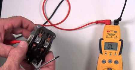
To test a contactor, check coil voltage, inspect for continuity across contacts, and verify proper operation with a multimeter. Ensure power is off before testing. These steps help identify failure in HVAC or motor circuits.
How to Test a Contactor?
A contactor test ensures the device operates correctly and safely in electrical systems. Follow these key steps:
✅ Check coil voltage and verify it matches the contactor's rating
✅ Use a multimeter to test continuity across power and auxiliary contacts
✅ Inspect for mechanical movement and clean contact surfaces if needed
Visit Our Electrical Troubleshooting Training Course
How to Test a Contactor is a critical procedure in diagnosing and ensuring the reliability of electrical systems, especially in air conditioning and heating applications. When they fail, they can cause system breakdowns, continuous running, or intermittent performance, which can be costly and unsafe. Testing allows electrical workers to verify its operational integrity, pinpoint potential issues, and determine if a replacement or repair is necessary. This article outlines a clear, step-by-step approach to safely and accurately test a contactor using a multimeter, empowering workers to maintain efficient and dependable equipment performance. For a deeper understanding of the tools involved in this process, see our electrical test equipment guide, which covers essential instruments for accurate insulation resistance testing.
Understanding the Purpose of a Contactor
It is a device used to manage electrical flow within a system. In air conditioning units, it regulates the connection between various components, like compressors and fans, to control cooling and heating. When the unit is powered on, it responds to a low-voltage signal, activating a magnetic field that enables higher-voltage connections. There are two primary types of contactors: single-pole and double-pole. Single-pole types have one magnetic coil for one circuit, while double-pole ones include two coils for dual-circuit connections. Recognizing these distinctions is important for accurate testing. The accuracy of an insulation resistance test depends on using the right device—learn more in our insulation resistance tester article.
Symptoms of a Malfunctioning Contactor
A failing contactor may cause various operational issues, such as continuous running, clicking sounds, or visible wear and tear. Continuous running might indicate a stuck unit, causing the air conditioner to remain active. Clicking sounds can result from electrical problems, but could also point to thermostat or compressor issues. Additionally, physical damage, known as pitting, often occurs from temperature extremes or debris, potentially leading to functional failures over time. By identifying these symptoms early, electrical workers can take preventive actions before major malfunctions occur. To implement a consistent maintenance schedule that includes insulation testing, read our preventive maintenance training overview.
Safety First: Power Isolation
Before performing any tests, ensure all power is disconnected from the contactor. Confirm with a voltage tester or multimeter. Electrical testing can be dangerous—follow safety protocols and wear appropriate PPE.
Step-by-Step Guide to Testing a Contactor
Using a multimeter is a standard method for testing. Here is a step-by-step process to guide you:
1. Remove Power to the Line Side
Turn off power to the line (L) side. Detach each wire, keeping them organized for reattachment later. Removing power from this side minimizes risk and enables accurate readings.
2. Detach Wires from the Terminal Side
Similarly, disconnect the wires on the terminal (T) side. Ensuring all wires are removed will prevent interference with the readings during testing.
3. Activate the Control Switch
Turn the control switch to the "on" position, listening for a click and a hum. This sound confirms that the magnetic coil is engaging correctly.
4. Set Up the Multimeter
Connect the multimeter’s red lead to the ohm terminal and the black lead to the common terminal. Turn on the multimeter, then touch the leads together to confirm a 0-ohm reading.
5. Line-to-Terminal Continuity (0 Ω)
To evaluate each line-to-terminal connection, place the red lead on L1 and the black lead on T1. A correct connection should show a 0-ohm reading. If the reading varies, it suggests an issue with that segment.
6. Verify Coil Activation
Engage the control switch to test the coil. The absence of an audible click could mean the coil is not receiving proper voltage or is defective.
7. Voltage Verification (e.g. 24 VAC)
To measure voltage, switch the multimeter to the voltage setting, placing the red lead to the volts terminal. Power the coil, and check each connector for the correct voltage. This step confirms the coil’s voltage integrity. If you're testing electric motors, visit our page on electric motor testing to explore diagnostic techniques that help detect insulation breakdown.
8. Testing Coil Resistance (10–100 Ω)
To evaluate the condition of the contactor coil, begin by removing all power from the system and disconnecting the coil wires. Set your multimeter to the resistance (ohms) setting.
-
Place one probe on each of the coil terminals.
-
A healthy coil should show a resistance value typically between 10 and 100 ohms, depending on the model and manufacturer specifications.
-
Readings below 10 ohms may indicate a shorted coil, while readings above 100 ohms (or infinite resistance) suggest an open or damaged coil.
This test helps confirm whether the coil is intact or needs replacement. Always refer to the equipment’s documentation for precise resistance values.
When to Replace the Contactor or Coil
If the coil fails resistance tests, voltage is absent, or contacts are pitted or burnt, replacement is usually required. If continuity tests fail or the coil doesn’t engage with power applied, replace the contactor for safety and performance.
After removing coil wires, switch the multimeter to the ohms setting. Place each lead on the coil’s connectors; the expected reading should fall between 10 to 100 ohms. A lower or higher reading indicates a potential defect in the coil.
If the testing reveals issues with the contactor or coil, replacing the faulty parts can restore the system’s reliability and efficiency. A functioning device ensures the electrical flow in air conditioning systems remains stable, supporting both performance and energy efficiency. Visit our NFPA 70B Testing and Maintenance Training course for more information.
Related Articles
Checking Insulation Resistance
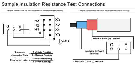
Checking insulation resistance ensures safe operation of electrical systems by detecting moisture, degradation, or leakage currents. It’s essential for preventing equipment failure and maintaining high dielectric quality in cables, motors, and switchgear.
Why Are We Checking Insulation Resistance?
Checking insulation resistance is the process of testing electrical insulation to ensure reliability, prevent shock hazards, and maintain system performance. It:
✅ Detects moisture, aging, or breakdown in insulation
✅ Prevents electrical failures and equipment hazards
✅ Commonly used on motors, cables, and switchgear
Regular dielectric resistance testing is a crucial component of maintaining the integrity and safety of electrical insulation systems. This testing helps identify potential issues such as short circuits or degraded non-conductive material that could lead to failures. By performing these tests as part of a preventive maintenance routine, facilities can ensure that their systems operate efficiently and safely. To perform accurate IR testing, it's essential to use a reliable insulation resistance tester designed specifically for assessing the health of dielectric materials in motors, cables, and electrical panels.
What is the purpose of checking insulation resistance in electrical systems?
The primary purpose of conducting an insulation resistance (IR) test is to assess the condition of the electrical insulation protecting conductors and components within a system. Over time, the insulating layer can degrade due to factors such as environmental stress, aging, and exposure to moisture, which can result in short circuits or reduced system efficiency. By identifying potential weaknesses in the insulation, maintenance teams can take proactive measures to prevent unexpected failures and ensure the ongoing reliability of their electrical systems.
The Institute of Electrical and Electronics Engineers (IEEE) standard 43, "Recommended Practice for Testing Insulation Resistance of Electric Machinery," advises that all resistance readings be adjusted to a standardized temperature of 40°C (104°F). This consistent temperature provides a reliable baseline, allowing for meaningful historical comparisons over time. Discover the importance of preventive maintenance in prolonging equipment life and preventing costly failures caused by dielectric material breakdown.
What are the steps when checking insulation resistance?
The process of conducting an IR test begins by ensuring that the equipment being tested is de-energized to prevent accidents. After verifying that the system is safe to work on, insulation resistance testers are used to apply a specified test voltage across the dielectric material. The resistance measurements obtained during the test provide valuable insight into the condition of the insulation. Additionally, a polarization index (PI) test may be performed, which involves taking two separate measurements—one after 60 seconds and another after 10 minutes—to assess the dielectric absorption capabilities of the protective coating. The test results are then compared to industry standards or historical data for the specific equipment.
What are acceptable insulation resistance values for different types of electrical equipment?
Acceptable values for an IR test vary depending on the type of equipment and the system voltage. Typically, higher resistance measurements indicate better dielectric quality, with megohm values often used as the benchmark. For example, large industrial motors or high-voltage transformers may require a minimum of 1 megohm per kilovolt of operating voltage. However, the test results need to be interpreted in context, considering factors such as the age of the equipment and the environment in which it operates. As part of a predictive maintenance strategy, our electric motor testing guide explains how insulation resistance measurements can reveal early-stage deterioration in windings.
How often should insulation resistance be checked?
The frequency of insulation resistance testing depends on the critical nature of the equipment and its operating conditions. For critical infrastructure, testing should be performed as part of a regular preventive maintenance schedule, typically once a year or more frequently if the equipment is exposed to harsh environments. High-voltage systems and those operating in wet or dusty conditions may require more frequent testing to ensure the dielectric material remains intact and effective.
Key Factors in Checking Insulation Resistance
| Category | Details |
|---|---|
| Purpose of IR Testing | Detect degradation, moisture intrusion, aging, and leakage paths |
| Test Instrument | Insulation Resistance Tester |
| IEEE Standard Reference | IEEE Std 43 – Test values normalized to 40°C (104°F) for consistency |
| Minimum Resistance Values | ≥1 MΩ per kV of rated voltage (e.g., 5 kV = 5 MΩ minimum) |
| Test Voltage Range | 500 V to 5,000 V DC (varies by equipment type and voltage class) |
| Test Types | Spot Reading, Time-Resistance Method, Polarization Index (PI) |
| PI Ratio (10-min / 1-min reading) | ≥2.0 (good insulation), 1.0–2.0 (marginal), <1.0 (potential issue) |
| Frequency of Testing | Annually or more often in harsh, high-voltage, or mission-critical systems |
| Environmental Influences | Temperature, humidity, contamination, equipment age |
| Common Applications | Motors, generators, cables, switchgear, transformers |
What factors can affect the accuracy of insulation resistance test results?
Several factors can influence the accuracy of an insulation resistance IR test. Temperature, humidity, and contamination can cause fluctuations in resistance measurements, leading to inaccurate assessments. For instance, moisture can lower the resistance value, suggesting degradation when the actual issue is environmental in nature. Similarly, the age of the equipment and the condition of the dielectric material can also impact test outcomes. Properly accounting for these variables during testing ensures that the test results accurately reflect the insulation's condition. IR testing is just one of many procedures outlined in our comprehensive electrical testing resource, which covers the key tools and methods used in field diagnostics.
Insulation resistance testing is a critical component of electrical system maintenance. By regularly performing IR tests and carefully analyzing the test results, maintenance teams can identify potential issues before they result in costly failures. Ensuring that equipment is properly de-energized and following standardized procedures for testing helps achieve accurate and reliable measurements, ultimately improving the longevity and safety of the electrical system.
Related Articles
What is Preventive Maintenance?
What Is Preventive Maintenance? A proactive approach for electrical systems using inspections, testing, lubrication, and calibration to reduce downtime, improve reliability, extend asset life, and meet NFPA 70B/IEC standards with CMMS-driven schedules and condition monitoring.
What Is Preventive Maintenance?
Planned electrical upkeep using inspections and testing to prevent failures, maximize uptime, and ensure code compliance.
✅ Schedules PM for switchgear, transformers, relays, and cables
✅ Uses infrared scans, insulation tests, and thermography
✅ Aligns with NFPA 70B, IEC 60364, and IEEE 3007 guidance
Preventive maintenance is a crucial aspect of equipment management that offers numerous benefits, including improved reliability, reduced downtime, and better asset management. By implementing a well-structured maintenance plan and leveraging available tools and software, organizations can optimize their operations and ensure the long-term success of their equipment maintenance programs. To build organizational capability, teams can leverage targeted preventive maintenance training that standardizes practices and improves consistency across sites.
In today's fast-paced world, keeping equipment running smoothly and efficiently is vital for organizations across various industries. One of the most effective ways to achieve this goal is through preventive maintenance, a practice that ensures equipment's proper functioning and longevity. This article will dive into preventive care, its benefits, and the essential components of an effective maintenance program. In manufacturing, utilities, and facilities management, comprehensive industrial electrical maintenance programs help align day-to-day tasks with long-term reliability goals.
Preventive maintenance is a systematic approach to maintaining equipment by performing routine tasks and inspections to prevent equipment breakdowns, increase reliability, and extend the operational life of assets. This proactive strategy focuses on maintaining equipment in optimal working condition to avoid unexpected failures and reduce downtime. Many organizations align their procedures with NFPA 70B 2023 to ensure maintenance activities meet recognized best practices and safety expectations.
One of the main benefits of adopting a preventive maintenance program is improved equipment reliability. Regularly scheduled maintenance tasks and inspections help identify potential issues before they escalate into costly failures. This, in turn, minimizes downtime, increases production efficiency, and reduces overall maintenance costs. Regular routes often include periodic electrical testing to validate equipment condition and detect degradation before it impacts operations.
Another key advantage is the role that preventive maintenance plays in asset management. By implementing a well-structured maintenance plan, organizations can better understand the current condition of their assets, predict equipment life cycles, and make more informed decisions regarding replacements and upgrades. Linking asset records with structured electrical troubleshooting procedures helps teams interpret failure modes and refine replacement strategies.
Creating a preventive maintenance plan requires a systematic approach, beginning with identifying all equipment and assets that need maintenance. Organizations should then develop a maintenance schedule based on the manufacturer's recommendations, historical data, and specific operational requirements. A comprehensive plan should also include procedures for routine inspections, equipment cleaning, component replacement or repair, and guidelines for documentation and record-keeping. Typical routines may specify checking insulation resistance on critical circuits to benchmark health and schedule timely interventions.
A common question when discussing preventive maintenance is the difference between this approach and predictive maintenance. While both strategies focus on preventing equipment failure, predictive maintenance uses advanced technologies and data analysis to predict when a component is likely to fail. This allows organizations to schedule maintenance only when necessary, thus optimizing resources and minimizing downtime. For rotating assets, periodic electric motor testing supports both preventive and predictive approaches by revealing trends in winding and bearing condition.
The essential components of a preventive maintenance program include a well-defined maintenance schedule, documentation and record-keeping systems, trained personnel, and appropriate tools and technologies. In addition, a successful program should be flexible and adaptable, allowing organizations to adjust based on feedback, performance metrics, and evolving needs.
Determining the frequency of preventive maintenance tasks depends on various factors, such as the type of equipment, its usage, environmental conditions, and manufacturer's recommendations. Maintenance should generally be performed regularly to ensure the equipment remains in optimal working condition.
Organizations can take advantage of various tools and software solutions available in the market to streamline the preventive maintenance process and improve efficiency. These technologies can help automate the scheduling of maintenance tasks, generate reports and analytics, track inventory and spare parts, and facilitate communication among team members.
Related Articles
How to Use a Digital Multimeter
How to use a digital multimeter? Learn to measure AC/DC voltage, current, and resistance, test continuity and diodes, select ranges or autoranging, place probes safely, and troubleshoot circuits with accurate readings and safety best practices.
How to Use a Digital Multimeter?
Measure V, A, and resistance; run continuity and diode tests safely.
✅ Set range or use autoranging before contacting probes
✅ Insert black to COM, red to V/ohm/mA; select AC or DC
✅ Verify continuity, diode drop, and resistance; note polarity
How to Use a Digital Multimeter?
Digital multimeters are used to solve most electrical problems - at the hands of a qualified electrical test profession. In fact, With a good wiring diagram and a good meter, a trained electrical professional can find the cause of almost any problem.
There are two basic types of multimeters, digital and analog. Analog multimeters have a needle and DMs have an LCD or a LED display. WIth today's demand for accuracy in testing electrical systems, it makes more sense to have a digital multimeter but an analog multimeter still has its uses.
This article focuses on DMs. A Digital multimeter will have many functions built into it. As with any tool or piece of equipment, it is necessary to make certain you read and follow digital multimeter instructions and cautions. This will protect you and your electrical equipment. If you still work with legacy needle gauges, a quick refresher on analog multimeters can help you understand when their response characteristics are advantageous in specific tests.
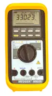
They will test for voltage, current and resistance. These are the three functions needed when trying to diagnose a problem. When you purchase a digital multimeter, one of the most important things to look at is the meter's impedance, which is the meter's operating resistance. Most digital multimeters have very high impedance. Since the meter is part of the circuit being tested, its resistance will affect the current flow through that circuit.
Typical Amperage Test
Digital multimeters can have very high impedance or resistance and they will cause a slight increase in the circuit's current. This becomes a concern when you test electronic systems because the increased current draw can damage the components being tested or, at the very least, alter the readings or change a sensor signal. It's best to get a meter that has an impedance of at least 10 megaohms. That way the current draw is so low it becomes invisible. Almost all meters have an "auto-range" features that will automatically select the proper range. Some meters will let you override this feature and let you manually select the range you want. Some DMMs do not have this option and must be set manually. Check the documentation that came with your digital multimeter and make sure you know and understand its different ranges.
Most meters that have an auto-range will have the setting either before or after the reading. Ohms are measured in multiples of ten and given the designation 'K' or 'M' with 'K' standing for 1,000 ohms and 'M' standing for 100,000,000 ohms. Amps would be displayed as mA, milliamps or 1/1000 of an amp or A for full amps. Volts will also be displayed as mV or volts. When you take a reading with a Digital multimeter that has auto-range, be sure you note at what range the meter is on. You could mistake 10 mA as 10 amps. Evaluating meter burden and circuit behavior is part of sound electrical testing practice to prevent misleading readings and component stress.
When readings seem inconsistent across ranges, structured electrical troubleshooting steps can isolate whether the issue is technique, setup, or a faulty component.
Typical Voltage Test
Most Digital multimeters that have auto-range will show the reading with a decimal point. A reading of 1.2 amps will be 12 amps if you ignore the decimal point.
Digital Multimeters do have a limit on how much current they can test. Usually this limit is printed at the point where the red lead plugs into the meter. If it says, "10 Amps Max" then there is a 10-amp fuse inside the meter that will blow if the current is above 10 amps. If you take out the 10-amp fuse and put in a 20-amp fuse, you will burn out the meter beyond repair. I would suggest buying a DMM that will handle at least 20 amps for automotive testing.
Typical Resistance Test
Another useful function of the Digital multimeters is the ohmmeter. An ohmmeter measures the electrical resistance of a circuit. If you have no resistance in a circuit, the ohmmeter will read 0. If you have an open in a circuit, it will read infinite.
An ohmmeter uses its own battery to conduct a resistance test. Therefore there must be no power in the circuit being tested or the ohmmeter will become damaged.
When a component is tested, the red lead is placed on the positive side and the black lead on the negative side. Current from the battery will flow through the component and the meter will determine the resistance by how much the voltage drops. If the component has an open the meter will flash "1.000" or "OL" to show an open or infinite resistance. A reading of 0 ohms indicates that there is no resistance in the component and it is shorted. If a component is supposed to have 1,000 ohms of resistance and a test shows it has 100 ohms of resistance, which indicates a short. If it reads infinite, then it is open. For very high resistance values, a dedicated megohmmeter provides test voltages and sensitivity beyond a standard DMM for insulation assessments.
For insulation checks on cables and windings, an insulation resistance tester supplies controlled DC test voltage to reveal leakage paths reliably.
Comparing results over time using an electrical insulation resistance test procedure helps detect gradual moisture ingress or degradation before failure.
Before condemning a part as open or shorted, follow best practices for checking insulation resistance so that lead placement, temperature, and stabilization time are accounted for.
Related Articles
Electrical Insulation Resistance Test Explained
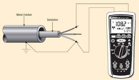
An electrical insulation resistance test measures the effectiveness of electrical insulation in resisting current flow. It helps detect degradation, moisture, or contamination in wiring, motors, and cables to prevent faults, ensure safety, and maintain equipment performance in industrial and commercial systems.
What is an Electrical Insulation Resistance Test?
An electrical insulation resistance test is ing the safety and ity of power systems.
✅ Measures the resistance of insulation to detect deterioration or moisture
✅ Ensures the safety and reliability of power systems and equipment
✅ Helps prevent faults in motors, cables, transformers, and wiring
Visit Our Electrical Troubleshooting Training Course
This test helps identify weaknesses in the insulation that can lead to equipment failure or dangerous faults. With around 80% of maintenance and testing involving evaluating the integrity of insulation, this analysis plays a critical role in maintaining system reliability. In this article, we will explore the importance of insulation resistance testing, how it is performed, and the factors that can affect the results. For a deeper understanding of the tools involved in this process, see our electrical test equipment guide, which covers essential instruments for accurate insulation resistance testing.
How to Interpret Results
Interpreting insulation resistance test results requires understanding what the measured resistance values reveal about the condition of the insulation. Typically measured in megohms (MΩ), these values indicate how well the insulation resists electrical current under applied test voltages. A higher resistance reading suggests good insulation health, while lower values may signal deterioration, contamination, or moisture ingress.
When using a megohmmeter, compare the results against the equipment manufacturer's specifications or industry standards like IEEE 43, which recommends a minimum resistance value of 1 megohm per kilovolt (1 MΩ/kV) plus 1 MΩ for rotating machines. For example, a 4,160V motor should generally show at least 5.16 MΩ. Resistance values well below this threshold may indicate dielectric breakdown or aging insulation.
It’s also important to observe resistance trends over time as part of a predictive maintenance program. A gradual decline in IR values could mean that the insulation is absorbing moisture or contaminants, while sudden drops may point to mechanical damage or insulation failure. Temperature corrections are essential when comparing results, as resistance tends to decrease with rising temperatures.
Consistently low readings across all test voltages could indicate uniform degradation, while varying results at different voltages may suggest surface leakage currents or partial discharges. In such cases, further diagnostic testing like polarization index (PI) or dielectric absorption ratio (DAR) may be required to assess insulation condition more accurately.
Proper interpretation of insulation resistance results helps ensure safe operation, reduce the risk of unplanned outages, and extend the life of electrical equipment.
Common Causes of Low Insulation Resistance Readings
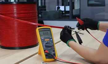
When insulation resistance readings fall below acceptable thresholds, it's critical to identify the underlying cause before resuming equipment operation. While a low megohm reading might suggest insulation failure, several other factors can also contribute.
One of the most frequent issues is moisture contamination. Water trapped inside insulation due to environmental exposure, poor sealing, or condensation can drastically reduce resistance values. Similarly, surface leakage currents caused by dust, oil, or conductive particles on the surface of insulators can give the false impression of degraded insulation.
Insulation aging is another major factor. Over time, thermal stress, electrical loading, and vibration can lead to insulation degradation, such as cracked jackets, hardened insulation, or reduced dielectric strength. In older equipment, these effects can cause gradual declines in resistance, which should be tracked and compared against historical maintenance records.
Ambient humidity and temperature during the test can also affect readings. High humidity tends to reduce resistance, especially on surfaces, while elevated temperatures can lower bulk insulation resistance. For accurate comparisons, apply temperature correction factors to normalize the results.
In some cases, improperly performed tests—such as using incorrect test voltages, poor grounding, or failing to isolate the system—can produce inaccurate results. Always follow manufacturer's instructions and test using calibrated megohmmeters to ensure reliability.
Understanding the cause of low readings allows for more accurate diagnosis, proper repairs, and targeted preventive maintenance—helping to avoid equipment damage, safety risks, and costly downtime.
Typical Minimum Insulation Resistance Values
| Equipment Type | Test Voltage | Minimum IR Value | Notes |
|---|---|---|---|
| Low-Voltage Motors | 500–1000 V DC | 1 MΩ or higher | Based on general guideline: 1 MΩ per kV + 1 MΩ |
| Medium-Voltage Motors | 1000–5000 V DC | 5 MΩ to 100 MΩ | Use IEEE 43 standard for rotating machines |
| Power Cables (LV) | 500–1000 V DC | >100 MΩ | Values depend on cable type and length |
| Power Cables (MV/HV) | 1000–5000 V DC | >500 MΩ | Higher resistance indicates dry, clean insulation |
| Dry-Type Transformers | 1000–5000 V DC | >1000 MΩ | Test phase-to-ground and phase-to-phase |
| Oil-Filled Transformers | 500–2500 V DC | >2000 MΩ | Check for oil contamination or moisture ingress |
| Control Wiring Circuits | 250–500 V DC | >10 MΩ | Lower voltages but still require good insulation |
| Switchgear Bus Insulation | 1000–5000 V DC | >1000 MΩ | Varies with voltage class and age of equipment |
Frequently Asked Questions
Why is it important?
An insulation resistance (IR) test measures the ability of insulation to resist current flow under high test voltages. It is important because it identifies potential faults in the insulation, such as moisture ingress, contamination, or degradation, which can lead to short circuits, equipment damage, or safety hazards. Regular preventative maintenance, including IR testing, helps ensure that systems remain safe and operational, reducing downtime and costly repairs.
How is an electrical insulation resistance test performed?
An IR test is typically conducted using insulation resistance testers, which apply high test voltages to the equipment's insulation. The process involves disconnecting the equipment from the power supply and applying the voltage across the insulation to measure its resistance to current flow. This analysis provides valuable resistance measurements that indicate the health of the insulation. The analysis is usually conducted at several voltage levels to assess performance under different conditions, and the results are compared to industry standards to determine if the insulation is performing correctly. If you're testing electric motors, visit our page on electric motor testing to explore diagnostic techniques that help detect insulation breakdown.
What are acceptable electrical insulation resistance test values?
Acceptable resistance measurements can vary based on the type of power system being tested. In general, higher resistance values indicate better insulation health, while lower values suggest potential problems. For example, large industrial motors may require minimum values of 1 megohm per kilovolt, while other systems might have different thresholds. Additionally, factors such as the type of equipment, system voltage, and environmental conditions can influence the acceptable value. It's important to follow industry guidelines when interpreting results. The accuracy of an insulation resistance test depends on using the right device—learn more in our insulation resistance tester article.
What factors can affect the results of an electrical insulation resistance test?
Several factors can impact the accuracy and reliability of insulation resistance testing. Temperature, humidity, and contamination can all lower resistance values, giving the appearance of insulation degradation when the issue may be environmental. Additionally, the age of the equipment and the condition of the dielectric can influence the results. Equipment that has been exposed to harsh conditions or has not been properly maintained may show lower resistance values due to dielectric absorption, where the insulation retains moisture or contaminants. It's important to account for these factors when evaluating analysis data. To implement a consistent maintenance schedule that includes insulation testing, read our preventive maintenance training overview.
How often should an electrical insulation resistance test be conducted?
The frequency of IR testing depends on the specific system and the operating environment. In general, critical systems should undergo IR testing as part of regular preventative maintenance, at least annually, though some equipment may require more frequent testing. For high-voltage equipment or equipment operating in harsh conditions, IR tests may need to be conducted more regularly to ensure safety and reliability. Ongoing monitoring of results helps in tracking any degradation in insulation performance over time, allowing for timely interventions.
An electrical insulation resistance test is a crucial aspect of maintaining the health and safety of power systems. Regular testing with appropriate resistance testers provides valuable insights into the integrity, helping to prevent costly failures and ensuring the safety of personnel. By understanding the factors that influence resistance measurements and following a consistent schedule, facilities can effectively manage the risk of failure and maintain reliable operations.
Related Articles
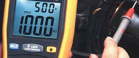
What is a Megohmmeter? A Great Testing Tool
What is a megohmmeter? An insulation resistance tester that applies high DC voltage to measure gigaohms, detect leakage current and dielectric integrity in cables, motors, transformers, and switchgear for safety, commissioning, and preventive maintenance.
What Is a Megohmmeter?
A megohmmeter measures insulation resistance using high DC voltage to reveal leakage paths and dielectric faults.
✅ Applies 250–1000 VDC to test insulation resistance up to gigaohms
✅ Detects leakage current, moisture ingress, and winding degradation
✅ Used for motors, cables, transformers, switchgear, and commissioning
What is a megohmmeter, and why should every electrical professional understand its importance? This specialized tool, also known as an insulation resistance tester, is critical for ensuring the safety and reliability of electrical systems in industrial, commercial, and institutional settings. By measuring high resistance values in electrical insulation, it helps detect potential faults, prevent equipment failures, and minimize costly downtime. In this article, we'll explore the key concepts and applications, including insulation integrity, fault detection, safety practices, testing procedures, and the role of megohmmeters in preventive maintenance programs. By understanding these crucial aspects, electrical professionals can enhance their skills in troubleshooting, maintenance, and safety protocols related to electrical systems. For a broader overview of specifications and use cases, the insulation resistance tester is well documented with practical guidance for field work.
To perform an insulation resistance test, the megohmmeter is connected to the conductor under test and a known reference point, typically ground. The device then applies DC voltages, typically within a specific voltage range, to the conductor and measures the resulting current flow. This resistance measurement, displayed in megohms, provides valuable information about the insulation's condition. A high resistance reading indicates that the insulation is in good condition and effectively preventing current leakage. To initiate the test, the operator simply presses the test button, and the megohmmeter applies the selected DC voltage. It's important to choose the appropriate voltage range based on the type of equipment and system voltage being tested. Detailed step-by-step methods are outlined in this electrical insulation resistance test reference that aligns with industry practice.
Insulation Integrity
The primary function of a megohmmeter is to assess the integrity of electrical insulation. Insulation acts as a barrier between conductors, preventing current leakage and ensuring the safe operation of electrical equipment. Over time, insulation can degrade due to factors like aging, heat, moisture, or chemical exposure. This degradation can weaken the dielectric strength of the insulation, increasing the risk of electrical breakdown. By measuring the insulation resistance, it provides valuable insights into the condition of the insulation and helps identify potential problems before they escalate. High insulation resistance values generally indicate good insulation quality, while low values suggest potential weaknesses that require further investigation or maintenance. Technicians can follow these checking insulation resistance recommendations to corroborate trends and spot early degradation.
Fault Detection
Megohmmeters are essential tools for detecting various types of insulation faults in electrical systems. One common fault is a ground fault, where a live conductor comes into contact with the ground or a grounded component. This can result in leakage current flowing to the ground, potentially causing electrical shocks or equipment damage. They can detect ground faults by measuring the insulation resistance between the conductor and ground. Another type of fault is a short circuit, where two conductors with different potentials come into contact, leading to a large current flow. While it might not directly detect a short circuit, it can identify insulation weaknesses that could eventually lead to one. By regularly testing insulation resistance, potential faults can be identified and addressed proactively, minimizing downtime and preventing costly repairs. Integrating insulation measurements with broader electrical testing routines helps correlate findings across protection, power quality, and asset health.
Safety Practices
Due to the high voltages involved in insulation resistance tests, safety is paramount when using a megohmmeter. Before conducting any tests, it's crucial to de-energize the electrical equipment and verify isolation to prevent electrical shocks. Additionally, any capacitive charge stored in the equipment should be discharged safely before and after testing. Operators should always use appropriate personal protective equipment, such as insulated gloves and safety glasses, to minimize the risk of electrical hazards. Following the manufacturer's instructions and established safety procedures is critical for ensuring the safe and effective use.
Testing Procedures
Proper testing procedures are essential for obtaining accurate and reliable results. Before conducting a test, it's crucial to select the appropriate testing voltage based on the type of equipment and the system voltage. The equipment under test should be disconnected from other circuits and properly grounded to prevent interference. The megohmmeter leads should be connected to the appropriate terminals, ensuring good contact. During the test, it's important to observe the reading and allow sufficient time for the insulation resistance to stabilize. The measured value should then be compared to the recommended values for the specific equipment and application. Any deviations from the expected values may indicate insulation degradation and require further investigation. Prior to applying high voltage, a digital multimeter can verify isolation and baseline continuity for safer setup.
Preventive Maintenance Programs
Megohmmeters play a vital role in preventive maintenance programs for industrial, commercial, and institutional power systems. Regular insulation resistance tests help identify potential problems before they lead to equipment failures or safety hazards. By incorporating megohmmeter testing into routine maintenance schedules, organizations can proactively address insulation degradation, extend the lifespan of electrical equipment, and minimize costly downtime. The frequency of testing depends on factors such as the type of equipment, its operating environment, and industry standards. However, regular testing, typically at least once a year, is crucial for ensuring the continued reliability and safety of electrical systems. In rotating equipment programs, standardized electric motor testing complements IR readings to track winding and insulation health over time.
Questions and Answers:
What is it used for?
It is primarily used to measure the insulation resistance of electrical equipment and systems. This helps assess the condition of the insulation and identify potential weaknesses that could lead to electrical faults or hazards.
What are the different types?
There are various types, including analog, digital, hand-cranked, and battery-powered models. They differ in their features, accuracy, and portability.
What is the difference between a megohmmeter and a multimeter?
While both measure electrical resistance, a megohmmeter is specifically designed to measure very high resistance values (megohms) using a high testing voltage. A multimeter typically measures lower resistance values and has other functions like measuring voltage and current. For basic diagnostics, traditional analog multimeters offer useful indication, though they are unsuited to high-megohm insulation checks.
How do you use one safely?
Safety precautions include de-energizing the equipment, discharging capacitive charge, using appropriate PPE, and following manufacturer instructions.
How do you interpret readings?
Higher resistance values generally indicate better insulation quality. Specific guidelines and acceptance criteria should be consulted for accurate interpretation.
They play a crucial role in maintaining the safety and reliability of industrial, commercial, and institutional power systems. These specialized instruments, also known as insulation resistance testers, are used to measure very high electrical resistance values, typically in the megohm (millions of ohms) range. By applying a high testing voltage, usually DC voltages between 500V and 5kV, a megohmmeter can assess the condition of electrical insulation in various components, such as cables, motors, transformers, and switchgear. This information is vital for detecting potential insulation weaknesses that could lead to electrical faults, equipment damage, or even safety hazards.


