Current Transformer Performance, Saturation and Protection Behavior
By Frank Baker, Technical Editor
By Frank Baker, Technical Editor

Our customized live online or in‑person group training can be delivered to your staff at your location.

Current transformers measure electrical current by reproducing primary current as a scaled secondary signal, but their performance under burden, saturation, and fault conditions determines protection accuracy, relay operation, and system reliability in electrical power systems.
Current transformers are used in electrical power systems to measure current, support protection relays, and provide safe monitoring of high-current circuits. Their performance directly affects how faults are detected, how quickly protection operates, and how accurately system conditions are interpreted. The performance of current measurement depends on how accurately the device reproduces the current flowing through the primary circuit.
In practice, a current transformer (CT) does more than scale current. It defines how the system interprets electrical conditions under normal load, transient events, and fault conditions. When performance is misunderstood, protection systems can misoperate, delays can occur, and measured data may not reflect the system's actual behavior.
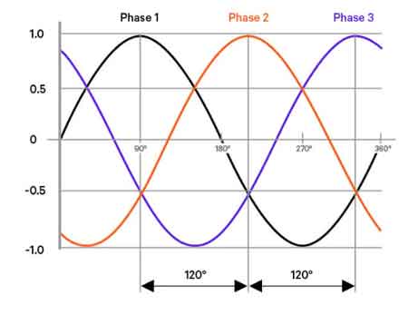
A current transformer operates by producing a magnetic field around the primary conductor, with current flowing through the primary circuit, inducing a corresponding current in the secondary winding.
The relationship is defined by the turns ratio between the primary and secondary windings, ensuring that the secondary current remains proportional to the primary current under normal conditions.
In practical installations, configurations such as bar type current transformers or split core current transformers influence how current is captured and how accurately the device responds under load or short circuit conditions, particularly when high fault current levels stress the magnetic core.
For a basic definition and operating principle, see What Is a Current Transformer.
Under normal operating conditions, a current transformer provides a proportional secondary current that closely reflects the primary conductor current. Protection relays and metering systems rely on this relationship to make decisions.

During fault conditions, however, current levels increase rapidly and may include DC offset components. These conditions stress the magnetic core and can alter the relationship between primary and secondary current. The result is not a loss of signal, but a distortion that affects how downstream devices interpret the event.
This distinction becomes critical in protection systems, where the timing and magnitude of relay operation depend entirely on the integrity of the current signal.
The accuracy of current measurement depends on how faithfully the current transformer reproduces the current flowing through the primary circuit.
Under fault conditions, the current seen by protection systems may differ from the actual current if the transformer saturates.
Current transformer saturation occurs when the magnetic core can no longer maintain a linear relationship between primary and secondary current. When this happens, the secondary current no longer accurately represents the primary waveform. Under high fault conditions, the current seen by protection systems may differ from the actual current if the magnetic core begins to saturate.
In protection applications, saturation can cause relays to see less current than is actually flowing. This may delay tripping, reduce fault sensitivity, or affect coordination between protective devices. Saturation is influenced by fault magnitude, burden, core design, and system conditions.
Understanding saturation in a current transformer is essential because it is not a device failure. It is a predictable operating limit that must be considered during system design and analysis.
A current transformer operates as part of a complete secondary circuit that includes wiring, relays, meters, and terminal connections. The total impedance of this circuit is referred to as the burden.
As burden increases, the CT must supply more voltage to maintain the secondary current. This increases the likelihood of error and accelerates saturation under high-current conditions. Even when the transformer itself is correctly specified, excessive burden from long cable runs or additional devices can degrade performance.
These characteristics align with the broader electrical constraints discussed in Transformer Ratings, where operating limits define performance boundaries.
Metering and protection applications impose different requirements on current transformers.
Metering CTs prioritize accuracy across normal operating ranges, where small deviations can accumulate into billing or reporting errors. Protection CTs prioritize performance under abnormal conditions, where maintaining signal fidelity during high fault currents is more important than fine measurement resolution.
A CT selected for metering may not perform adequately in protection applications if saturation occurs too early. Conversely, a protection CT may not provide the precision required for revenue metering. This distinction is fundamental to the correct application.
Installation practices directly influence how a current transformer performs in service. Improper grounding, incorrect polarity, or excessive secondary wiring length can introduce measurement error or instability.
An open secondary condition presents a serious hazard. If the secondary circuit is interrupted while primary current is flowing, high voltages can develop across the secondary terminals. Proper grounding and maintaining a closed circuit are essential for both safety and measurement integrity.
These installation considerations complement the isolation principles described in Isolation Transformer, although a current transformer serves a measurement role rather than voltage separation.
Current transformer performance is most critical in systems where accurate current interpretation drives operational decisions. Accurate current measurement is essential for relay coordination, system protection, and reliable monitoring of electrical systems.
Download our FREE Electrical Training Catalog and explore a full range of expert-led electrical training courses.

Key applications include:
Protective relays that depend on accurate fault current detection
Generator and feeder protection schemes requiring coordinated response• Revenue metering systems where measurement accuracy affects billing
Power system analysis and diagnostics relying on recorded current data
In these systems, the current transformer provides the signal that defines system behavior. This role works alongside voltage measurement devices such as the Potential Transformer, which supplies the corresponding voltage reference.
Current transformers operate as part of a broader measurement framework that includes both current and voltage sensing. Together, these devices enable protection and monitoring systems to interpret electrical conditions without direct exposure to high-energy levels.
This relationship is part of the overall structure of Instrument Transformers, where current and voltage measurement devices serve complementary roles within electrical power systems.
Advantages To Instructor-Led Training – Instructor-Led Course, Customized Training, Multiple Locations, Economical, CEU Credits, Course Discounts.
Request For QuotationWhether you would prefer Live Online or In-Person instruction, our electrical training courses can be tailored to meet your company's specific requirements and delivered to your employees in one location or at various locations.