Current Transformer Ratio Definition and CT Scaling Relationship
By Harold Williams, Associate Editor
By Harold Williams, Associate Editor
Our customized live online or in‑person group training can be delivered to your staff at your location.

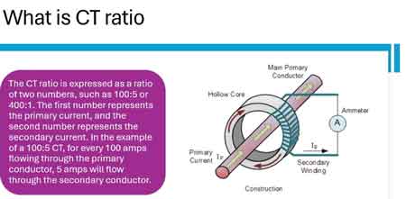
Current transformer ratio defines the relationship between the primary and secondary currents, typically expressed as ratios such as 300:5 or 600:1, enabling accurate current scaling for metering, protection relays, and safe measurement in electrical power systems.
A current transformer ratio reduces high primary current to a standardized secondary value, such as 5 A or 1 A, allowing meters, relays, and monitoring devices to operate safely and accurately. The ratio ensures that the current flowing in the primary circuit is accurately represented as a reduced current in the secondary circuit.
The ratio is expressed as the primary-to-secondary current, meaning that 300 amperes flowing in the primary circuit corresponds to 5 amperes in the secondary circuit. This relationship determines how current is scaled within electrical systems.
The current ratio represents a fixed proportional relationship and is a defining characteristic of how current is measured and interpreted in power systems.
The current transformer ratio indicates how many amperes in the primary circuit correspond to each ampere in the secondary winding. For example, a 600:5 ratio means the primary current is reduced by a factor of 120 to produce a measurable output.
This proportional scaling ensures that electrical instruments can safely measure current without being directly exposed to high current levels. The ratio is determined by the number of turns in the secondary winding relative to the effective primary turns.
To understand how the device itself operates, see What Is a Current Transformer.
The current transformer ratio is calculated by dividing the primary current by the secondary current:
CT ratio = Primary Current ÷ Secondary Current
Stay informed with our FREE Electrical Transformers Newsletter — get the latest news, breakthrough technologies, and expert insights, delivered straight to your inbox.
For example:
A 400:5 current transformer produces 5 amperes in the secondary circuit when 400 amperes flow through the primary circuit.
The effective ratio can change if the conductor is passed through the core multiple times. For instance, looping the primary conductor twice through a 100:5 current transformer results in an effective ratio of 50:5. This relationship allows high current levels to be converted into measurable current values suitable for instruments and protection devices.
Common CT ratios are selected based on system current levels and standard instrument requirements.
Typical ratios include:
Secondary currents are typically standardized at 5 A or 1 A to match metering and protection equipment requirements.
These standardized ratios ensure compatibility with devices that rely on consistent current scaling.
The selected current ratio directly affects measurement accuracy and system performance.
If the ratio is too high, the measured current may be too small to provide accurate readings under normal operating conditions.
If the ratio is too low, the transformer may be exposed to higher current levels than intended, increasing the risk of saturation and measurement error.
Accurate ratio selection ensures that both metering systems and protection relays receive reliable current signals. Accurate current scaling is essential for reliable system monitoring and protection performance.
The current transformer ratio defines how electrical current is interpreted by measurement and protection systems. It works alongside voltage measurement devices such as the Potential Transformer, which provides the corresponding voltage reference.
Together, these devices enable electrical systems to be monitored and controlled without direct exposure to high-energy levels.
Current transformer ratios are part of the broader framework of Instrument Transformers, which include both current and voltage measurement devices used in power systems.
Each device performs a specific role, with the CT ratio defining how current is scaled and interpreted within the system.
Think you know Electrical Transformers? Take our quick, interactive quiz and test your knowledge in minutes.
Explore 50+ live, expert-led electrical training courses –