


Unit of Capacitance Explained
Download Our OSHA 3875 Fact Sheet – Electrical PPE for Power Industry Workers

- Follow rules for rubber gloves, arc-rated PPE, and inspection procedures
- Learn employer obligations for testing, certification, and training
- Protect workers from arc flash and electrical shock injuries
The unit of capacitance is the farad (F), which measures the amount of electric charge a capacitor stores per volt. Typically expressed in microfarads, nanofarads, or picofarads, it is essential in electronics, circuit design, and energy storage systems.
What is a Unit of Capacitance?
The unit of capacitance, the farad (F), measures the amount of electric charge a capacitor can store per volt. It is crucial to understand the function of capacitors in electronics, circuits, and energy storage technologies.
✅ 1 farad equals 1 coulomb per volt
✅ Common values include microfarads, nanofarads, and picofarads
✅ Used in electronics, circuits, power systems, and capacitor design
It is determined by the electrical charge, which is symbolized by the letter Q, and is measured in units of coulombs. Discover how capacitance interacts with other electrical quantities and gain a deeper understanding of its role in circuit design and performance. The coulomb is given by the letter C, as with capacitance. Unfortunately, this can be confusing. One coulomb of charge is defined as a charge equivalent to 6.28 × 10^18 electrons. The basic unit is the farad, denoted by the letter F. By definition, one farad is the amount of charge stored on a capacitor when one volt is applied across its plates. The general formula for capacitance in terms of charge and voltage is:
Understanding the Unit of Electric Capacitance
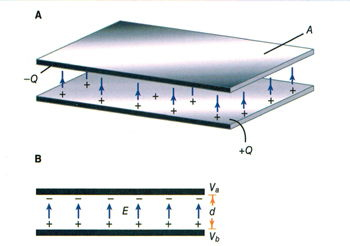
The unit of electric capacitance explains how a capacitor functions as a body to store an electrical charge. This is achieved through two conductive plates, which form the essential structure of a parallel plate capacitor. These plates are separated by an insulating material, known as the dielectric, which prevents direct current flow while allowing the device to store energy.
Test Your Knowledge About Electricity Questions!
Think you know Electricity Questions? Take our quick, interactive quiz and test your knowledge in minutes.
- Instantly see your results and score
- Identify strengths and areas for improvement
- Challenge yourself on real-world electrical topics
A capacitor is a widely used electronic component, and it belongs to the class of passive electronic components since it does not generate energy but only stores it temporarily. The concept of capacitance was first defined by the English physicist Michael Faraday, whose pioneering work in electromagnetism laid the foundation of electrical science. Historical records place Michael Faraday 1791 1867 as one of the most influential figures in this field.
In modern practice, capacitance is measured in the SI base units of the farad (F). Because a farad is large, smaller units such as the nanofarad nF are commonly used to describe practical capacitors found in circuits. Whether measured in farads, microfarads, or nanofarads, the unit of electric capacitance remains the standard way of expressing a capacitor’s ability to store charge for reliable operation in electronic systems.
Farad in Practical Use
In practical terms, one farad is a large amount of capacitance. Typically, in electronics, much smaller units are used. The two more common smaller units are the microfarad (μF), which is 10^-6 farad, and the picofarad (pF), which is 10^-12 farad. To better understand the core principles behind charge and voltage, see our overview on what is a capacitor, which explains how capacitance functions in practical circuits.
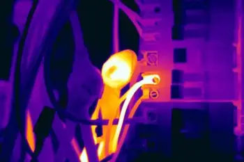
Voltage Rating of a Capacitor: Capacitors have limits on the voltage that can be applied across their plates. The aircraft technician must be aware of the voltage rating, which specifies the maximum DC voltage that can be applied without risking damage to the device. This voltage rating is typically referred to as the breakdown voltage, working voltage, or simply the voltage rating. If the voltage applied across the plates is too great, the dielectric will break down, and arcing will occur between the plates. The capacitor is then short-circuited, and the possible flow of direct current through it can cause damage to other parts of the equipment. For foundational knowledge that supports capacitance calculations, our what is voltage article defines the relationship between electric potential and stored charge.


A capacitor that can be safely charged to 500 volts DC cannot be safely subjected to AC or pulsating DC whose effective values are 500 volts. An alternating voltage of 500 volts (RMS) has a peak voltage of 707 volts, and a capacitor to which it is applied should have a working voltage of at least 750 volts. The capacitor should be selected so that its working voltage is at least 50 percent greater than the highest voltage to be applied. Learn about different types of components that influence total capacitance by reading our guide on types of capacitors, which compares materials, ratings, and applications.
Smaller Units of Capacitance
The voltage rating of the capacitor is a factor in determining the actual capacitance, as capacitance decreases with increasing dielectric thickness. A high-voltage capacitor with a thick dielectric must have a larger plate area to achieve the same capacitance as a similar low-voltage capacitor with a thin dielectric.
Table 1 – Dielectric Strength of Common Materials
| Dielectric Material | Approx. Dielectric Strength (kV/mm) | Relative Permittivity (εr) | Notes / Applications |
|---|---|---|---|
| Vacuum | 30 | 1.0 | Reference value, ideal insulator |
| Air | 3 | ~1.0 | Baseline, used as standard |
| Paper | 16 | 3–4 | Used in older capacitors |
| Glass | 9–14 | 4–10 | High stability, low loss |
| Mica | 100 | 5–7 | Precision capacitors, RF use |
| Ceramic | 10–40 | 6–12 (varies) | Common in small capacitors |
| Polystyrene | 20–30 | 2.5–2.7 | Low loss, stable |
| Polyethylene | 20–30 | 2.2 | High-voltage applications |
| Teflon (PTFE) | 60–170 | 2.1 | Excellent insulator, stable |
| Oil (transformer) | 10–15 | 2.2–2.3 | Used in HV capacitors and transformers |
| Quartz | 8–10 | ~3.8 | Stable, heat resistant |
Factors Affecting A Unit of Capacitance
-
The capacitance of parallel plates is directly proportional to the area of the plates. A larger plate area produces a larger capacitance, and a smaller area produces less capacitance. If we double the area of the plates, there is room for twice as much charge. The charge that a capacitor can hold at a given potential difference is doubled, and since C = Q/E, the capacitance is doubled.
-
The capacitance of parallel plates is inversely proportional to the spacing between them.
-
The dielectric material affects the capacitance of parallel plates. The dielectric constant of a vacuum is defined as 1, and that of air is very close to 1. These values are used as a reference, and all other materials have values specified in relation to air (vacuum).
The strength of some commonly used dielectric materials is listed in Table 1. The voltage rating also depends on frequency, as the losses and resultant heating effect increase with higher frequencies. Discover how capacitance fits into the broader context of energy flow in circuits by visiting our what is electrical resistance page, offering insights on resistance and its effect on voltage and current.
FREE EF Electrical Training Catalog
Download our FREE Electrical Training Catalog and explore a full range of expert-led electrical training courses.

- Live online and in-person courses available
- Real-time instruction with Q&A from industry experts
- Flexible scheduling for your convenience