There are many Electricity Questions for which students seek answers.
Electricity Questions

Single Electricity Market Explained
A single electricity market is not simply a trading framework. It is an operational system that determines how electric power is priced, dispatched, balanced, and financed across interconnected grids. When markets are unified, generation decisions, infrastructure investment, and reliability planning shift from national isolation to regional optimization. For system operators, regulators, and market participants, this structure directly shapes long-term cost, security of supply, and renewable integration outcomes.
What a Single Electricity Market Actually Does
A single electricity market unifies previously separate wholesale markets into a common scheduling, pricing, and settlement environment. Generators submit offers, suppliers submit demand, and a…
View more
What is an Electrical Circuit?
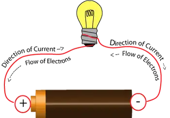
An electrical circuit is a closed loop that allows electric current to flow through conductors, power sources, and loads. Circuits connect electrical devices, enable energy transfer, and ensure safe operation in homes, industries, and power systems.
What is an Electrical Circuit?
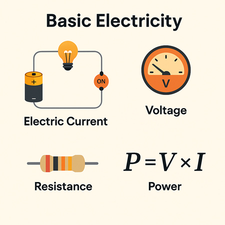
Gaining a grasp of the basic electricity of electrical circuits, including series and parallel configurations, voltage, current, resistance, Ohm's Law, and circuit analysis techniques, is vital for anyone interested in electronics, electrical engineering, or the inner workings of modern technology.
Core Components & Function
In order to understand what an electrical circuit is, one must appreciate that, …
View more

What is a Resistor?
A resistor is an electronic component that limits or regulates the flow of electric current, manages voltage levels, and safeguards circuits in electrical and electronic devices, ensuring stable performance and preventing component damage.
Understanding the Resistor
A resistor is an electronic component designed to create electrical resistance in a circuit, playing a key role in controlling how electricity behaves. By limiting or regulating the flow of electric current, a resistor helps control voltage levels so that electrical and electronic devices operate properly, while also protecting sensitive components from damage caused by excessive current.
In electronic components and circuits, resistors…
View more
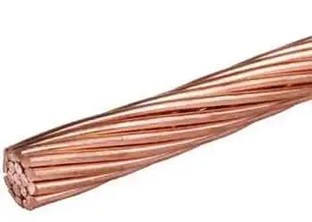
What is a Conductor?
A conductor is a material that allows electric current to flow easily because it has low electrical resistance. In electrical systems, this behavior occurs because conductors contain free electrons that move when voltage is applied, creating a controlled path for current through wires, cables, and circuit components.
Electrical conductors are essential for power distribution, signal transmission, and equipment operation. Without conductors, electricity could not be delivered, controlled, or used in practical applications. Copper and aluminum are the most common conductor materials because they combine high conductivity, durability, and cost efficiency.
A conductor is defined by how freely it permits electron…
View more
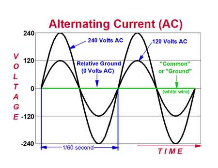
What Is Alternating Current?
Alternating current is an electric current that reverses direction at a set frequency, usually 50 or 60 hertz. AC powers homes, industries, motors, lighting, and grids because it can be transmitted over long distances.
What is Alternating Current?
Alternating current, commonly referred to as AC, is a form of electrical current in which the direction of charge flow reverses at regular intervals. Unlike direct current, which moves in one constant direction, AC oscillates back and forth. This change in direction allows AC to be generated efficiently, transmitted over long distances, and adapted to a wide range of voltage levels. …
View more
Electrical Short Circuit
An electrical short circuit occurs when current moves through an unintended low-resistance path, creating high fault current, arc energy, and safety hazards. Proper protection, grounding, and insulation reduce risks across electrical systems.
Electrical Short Circuit Overview and Best Practices
This dangerous event can result in power outages, damaged appliances, or even fires. By understanding the types of short circuits, their causes, detection methods, and prevention strategies, we can greatly reduce the risks. When studying short circuits, it is helpful first to understand the principles of basic electricity, as the same laws of voltage, current, and resistance explain why faults occur.
In…
View more
What Is Static Electricity?
Static electricity is the accumulation of electrical charge on an object’s surface, usually from friction, induction, or contact. This imbalance of electrons and protons creates sparks, shocks, and attraction, influencing physics, electronics, and everyday energy phenomena.
What is Static Electricity?
Atoms also consist of positively charged particles called protons and neutral particles called neutrons. When an object gains or loses electrons, it becomes positively or negatively charged.
How Static Electricity Forms
Static electricity occurs when a static electric charge builds up on the surface of a material, often resulting from friction or the separation of objects. This phenomenon,…
View more
What is Electric Load
Electric load refers to the amount of electrical power consumed by devices in a system. It determines demand on the power supply and affects energy distribution, efficiency, and system design.
What is Electric Load?
What is electric load? It refers to the total power demand placed on a circuit by connected devices. Electric load, such as lighting, motors, and appliances, impacts energy use, system sizing, and overall efficiency across residential, commercial, and industrial settings.
An electric load refers to any device or system that consumes electric power to perform work, such as an electric motor, lighting fixture, or household…
View more
What is an Arc Fault?
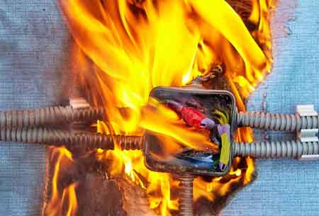
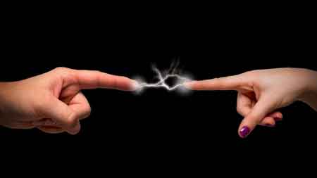
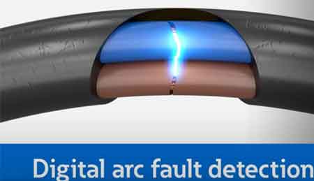
An arc fault is a dangerous electrical discharge between conductors or to ground. It generates intense heat and light, often caused by damaged insulation, frayed wires, or loose connections, posing major electrical safety and fire hazards.
What is an Arc Fault?
Basic Protection Relay Training
Short Circuit Study Training
Request a Free Training Quotation
Understanding Arc Faults and Electrical Safety
An arc fault is a hazardous electrical event that can lead to severe consequences, including fires and substantial property damage. Understanding how faults occur, how to prevent them, and why protective measures like Arc Fault Circuit Interrupters (AFCIs) are…
View more
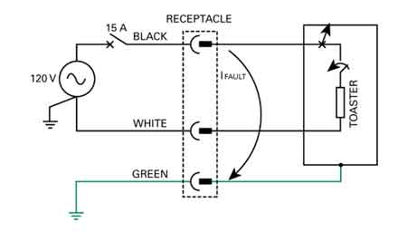
What is a Ground Fault? Hazard Explained
A ground fault occurs when electrical current leaves its intended circuit path and flows to ground through an unintended conductive route.
Understanding Ground Fault
When current follows an unintended path to ground, it creates conditions that can damage equipment and present serious shock hazards. These faults are commonly associated with insulation breakdown, wiring damage, or environmental exposure that alters normal current flow. Understanding how and why ground faults occur is essential for recognizing risk conditions before they lead to injury or system failure. Proper electrical grounding is essential to prevent ground faults, as it ensures stray currents are safely diverted…
View more
What is Considered High Voltage? HV Applications Explained
What is considered high voltage? Per IEC/IEEE, voltages above 1 kV AC or 1.5 kV DC; linked to insulation coordination, arc-flash risk, transmission lines, substations, switchgear ratings, clearance/creepage distances, and dielectric breakdown in power systems.
What Is Considered High Voltage?
What is Considered High Voltage?In the world of electrical engineering, understanding voltage levels is crucial. So you might be asked to define high voltage. But what is considered HV? This article explores the definition, classification, and applications of HV and the safety concerns and precautions that come with it. For foundational context, the concept of voltage underpins how these…
View more
What is Low Voltage?
Low voltage refers to electrical systems operating at 50 to 1000 volts AC or 120 to 1500 volts DC. Common in residential, commercial, and control circuits, it reduces shock risks while powering lighting, HVAC, security systems, and automation equipment safely.
What is Low Voltage?
In today's technologically driven world, understanding the concept of low voltage (LV) is essential. Low voltage systems are widely used across industries, homes, and offices, making them an integral part of our daily lives. This article provides an overview of LV, its applications, safety measures, and regulations, incorporating the keywords provided. Low voltage systems…
View more
What is a Voltage Regulator?
What is a voltage regulator? A control circuit that stabilizes DC output from AC/DC power supplies using feedback, reference, and PWM; includes linear LDOs and switching buck/boost converters, improving line/load regulation, ripple suppression, efficiency.
What Is a Voltage Regulator?
What is a voltage regulator, and how does it work?A voltage regulator is a component of the power supply unit that maintains a constant voltage supply through all operational conditions. Voltage regulators can regulate both AC and DC voltages, ensuring a steady, constant voltage supply. The output voltage is usually lower than the input voltage. The regulator compares the output…
View more
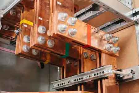
What is a Busbar?
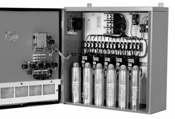
A busbar is a rigid conductor, typically made of copper or aluminum, that serves as a common connection point for multiple circuits within electrical enclosures. It provides a low-resistance path for high current, reduces wiring complexity, and improves thermal and mechanical stability in power distribution systems.
What is a Busbar: Overview
In an electrical system, power is not only controlled by breakers and switches. It is physically guided by the conductors that carry it between those devices. The busbar exists to perform that role with precision, stability, and predictability.
A busbar is a rigid conductor, typically made of copper…
View more
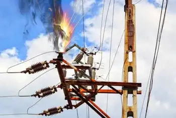
What is an Electrical Fault?
An electrical fault occurs when a system or piece of equipment departs from its normal operating state, resulting in abnormal current flow. This can result in overheating, equipment damage, or safety risks. Protective devices isolate faults to preserve safety and reliability.
What is an Electrical Fault?
Electrical faults can occur for various reasons, including equipment failure, environmental conditions, and human error. Some common causes of electrical faults include faulty wiring, damaged insulation, overloaded circuits, lightning strikes, power surges, and voltage fluctuations.
Equipment issues: faulty wiring, broken insulation, overloaded circuits
Environmental conditions: moisture, lightning, dust, or tree contact
Human error:…
View more
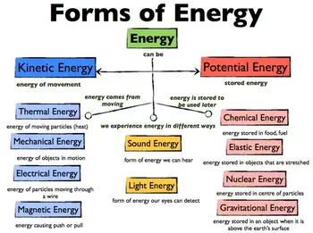
What is Energy?
Energy is the capacity to do work, powering motion, heat, and electricity. It exists in many forms—kinetic, potential, chemical, thermal, and renewable—transforming constantly to sustain life, industry, and the universe itself.
What is Energy?
To fully understand what energy is, it helps to start with Basic Electricity, which explains the foundation of how electrical systems operate in daily life.
It can be created or released through chemical reactions, nuclear reactions, and electromagnetic waves. Energy is classified into various types based on its origin, nature, and form, including mechanical, thermal, chemical, electrical, radiant, gravitational, nuclear, and sound. With the rise of…
View more
Who Discovered Electricity
Who discovered electricity? Early pioneers including William Gilbert, Benjamin Franklin, Luigi Galvani, Alessandro Volta, and Michael Faraday advanced static electricity, circuits, and electromagnetism, laying the foundation for modern electrical science.
Who Discovered Electricity?
From the writings of Thales of Miletus it appears that Westerners in their day knew as long ago as 600 B.C. that amber becomes charged by rubbing. But other than that, there was little real progress until the English scientist William Gilbert in 1600 described the electrification of many substances and coined the term "electricity" from the Greek word for amber. For a deeper look at…
View more
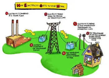
How Electricity Works
Electricity works by moving electrons through a conductor, creating an electric current. Power stations generate electricity, which travels through wires to homes and businesses. This flow powers devices, lights, and machines, making modern life possible through electric energy and circuits.
Explain How Electricity Works
What Is Electricity and Where Does It Come From?
Electricity energy is as common to us as running water in many areas, especially in industrialized countries. Despite this, there is a great deal of ignorance about this mysterious force and its origin.
The concept of voltage is central to how electricity flows, as it represents…
View more
Define Electromagnetism
Electromagnetism is the branch of physics that studies the interaction between electric currents and magnetic fields. It explains how electricity generates magnetism and powers devices such as motors, generators, and transformers in modern electrical systems.
Define Electromagnetism: Real-World Examples and Uses
The electromagnetic force is carried by electromagnetic fields, which are composed of electric fields and magnetic fields, and it is responsible for electromagnetic radiation, such as light.
Who Discovered Electromagnetism?
In 1820, the Danish physicist, Hans Christian Oersted, discovered that the needle of a compass brought near a current-carrying conductor would be deflected. When the current flow…
View more
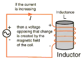
Understanding Inductance
Inductance is an electrical property that resists changes in current by storing energy in a magnetic field. It occurs in inductors, coils, and AC circuits, where inductive reactance affects voltage, current flow, and circuit behavior.
Inductance History
Michael Faraday discovered that moving a magnet through a coil of wire induces a voltage across the coil. If a complete circuit were provided, a current would also be induced. The amount of induced voltage is directly proportional to the rate of change of the magnetic field with respect to the coil. The simplest experiment shows that when a bar magnet is…
View more
Types of Capacitors
The types of capacitors vary by design and application, including ceramic, electrolytic, film, and supercapacitors. Each offers unique benefits for electronics, power supply circuits, energy storage, and filtering needs.
Why Understanding Types of Capacitors Is Important
There are various types of capacitors. They are electronic components of electric filters and tuned circuits that store and release electrical energy. They consist of two conductive plates separated by a dielectric material. When a voltage is applied across the plates, an electric field is created between them, and an electrical charge accumulates on the plates. It represents the distance between the plates.…
View more
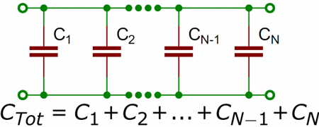
Capacitance in Parallel Explained
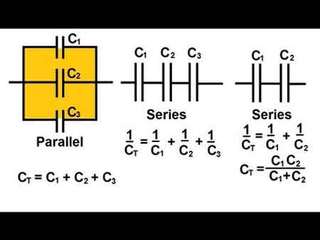
Capacitance in parallel occurs when capacitors are connected side by side, and their values add together. This increases total capacitance, ensures stable voltage, supports efficient charge distribution, and is essential in electronics, energy storage, and reliable circuit design.
A Practical Guide to Capacitance in Parallel
To learn the fundamentals, see what is capacitance, which explains how capacitors store charge, the role of farads, and why this property is essential in circuits and energy storage.
Understanding Parallel Capacitor Behavior
When capacitors are connected in parallel, the effective plate area increases, and the total capacitance is the sum of the individual…
View more
Unit of Capacitance Explained
The unit of capacitance is the farad (F), which measures how much electric charge a capacitor stores for each volt of applied voltage.
The governing equation is:
C = Q / V
where C represents capacitance measured in farads, Q represents electric charge measured in coulombs, and V represents voltage measured in volts. This relationship defines how capacitors store electrical energy within electric fields.
In practical circuits, capacitance determines how components store energy, filter signals, smooth power supplies, and stabilize voltage levels. Because one farad represents a very large storage capacity, most electronic components use smaller units such as microfarads…
View more
Capacitance Definition
Capacitance definition clarifies how a capacitor stores electric charge per unit voltage, measured in farads, influenced by plate area and dielectric, shaping reactance, energy storage, and signal behavior in AC and DC circuits.
Understanding Capacitance Definition: Principles and Applications
Capacitance DefinitionAnother important property in AC electronic circuits, besides resistance and inductance, is capacitance. Capacitance is measured in units. The unit of capacitance is the farad. While inductance is represented in a circuit by a coil, capacitance is represented by a capacitor. In its most basic form, the capacitor is constructed of two parallel plates separated by a nonconductor, called…
View more
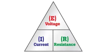
What is Ohm's Law?
Ohm’s Law explains the relationship between voltage, current, and resistance in electrical circuits. Using a simple formula, it helps predict current flow, calculate voltage drop, size conductors, and troubleshoot both AC and DC electrical systems.
What is Ohm's Law as a Fundamental Principle
When asking what is Ohm’s Law, it is useful to compare it with other fundamental rules like Kirchhoff’s Law and Ampere’s Law, which expand circuit analysis beyond a single equation.
Ohm’s Law describes the simple relationship between voltage, current, and resistance in any electrical circuit. It shows why current rises when voltage increases, why resistance limits…
View more
What is Electricity?
Electricity is the controlled movement of electric charge through materials, allowing energy to be transported, regulated, and converted into light, heat, motion, and stored chemical energy in modern electrical systems.
What Is Electricity
Electricity is the controlled movement of electric charge through a material. In practical systems, this movement occurs when electrons drift through a conductive path under the influence of an electric field, or voltage. When that movement follows a complete circuit, energy can be transferred, regulated, and converted into useful forms such as light, heat, motion, or stored chemical energy.
Electricity is neither a substance nor a…
View more
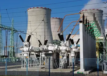
How Is Electricity Generated?
It is produced by converting various energy sources, such as fossil fuels, nuclear, solar, wind, or hydro, into electrical energy using turbines and generators. These systems harness mechanical or chemical energy and transform it into usable power.
Understanding Electricity Generation
Electricity generation is the lifeblood of modern civilization, powering homes, industries, hospitals, transportation systems, and digital infrastructure. But behind the flip of a switch lies a vast and complex process that transforms raw energy into electrical power. At its core, electricity is generated by converting various forms of energy, mechanical, thermal, chemical, or radiant, into a flow of electric…
View more
Electricity How it Works
Electricity How It Works explains electron flow, voltage, current, resistance, and power in circuits, from generation to distribution, covering AC/DC systems, Ohm's law, conductors, semiconductors, transformers, and energy conversion efficiency and safety.
The Science Behind How Electricity Works
Electricity How It Works - This is a very common question. It can best be explained by stating this way: Single-phase electricity is what you have in your house. You generally talk about household electrical service as single-phase, 120-volt AC service. If you use an oscilloscope and look at the power found at a normal wall-plate outlet in your house, what you…
View more
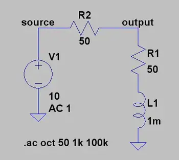
What Is Impedance in AC Circuits?
Impedance is the total opposition that an alternating current (AC) circuit presents to the flow of electric current, combining resistance and reactance into a single quantity measured in ohms (Ω). It defines both the amount of current that flows and the phase relationship between voltage and current. The relationship is given by Z = √(R² + X²), where R is resistance and X is reactance.
Impedance applies specifically to AC circuits because changes in current introduce frequency-dependent effects that do not exist in steady direct current systems. Resistance represents real opposition to current, while reactance represents opposition caused by energy…
View more
What is Inductance?
Inductance is the property of an electrical circuit that resists changes in current by storing energy in a magnetic field. It underpins transformers, motors, inductors, and AC power systems, making it essential in the field of electrical engineering.
What is Inductance?
This principle is central to electromagnetic induction and underlies many devices in modern power and electronics.
The principle of inductance was first discovered by Michael Faraday, who showed that moving a magnet through a coil of wire induced a voltage across the coil. This discovery, known as Faraday’s Law, explains the phenomenon of electromagnetic induction. Heinrich Lenz later refined…
View more
What is Current Electricity?
Current electricity is the flow of electric charge through a conductor, measured in amperes and given by the relationship I = V/R between voltage, resistance, and current. It describes how electrons move in circuits, including AC and DC behavior, enabling circuit operation.
Current electricity is the continuous movement of electric charge through a conductive path within a closed circuit, driven by a voltage difference that creates an electric field and causes electrons to move. The rate of this movement is measured in amperes and depends on the balance between applied voltage and circuit resistance, expressed by Ohm’s Law as I…
View more
What is an Ampere?
An ampere is the standard unit for measuring electric current. It describes how much electric charge moves through a conductor over time and provides a practical way to quantify current flow in electrical and electronic systems.
Overview: What is an Ampere?
Electric current is the movement of charged particles, usually electrons, through a circuit. When current flows, energy is delivered to devices such as lights, motors, heaters, and electronics. The ampere provides a universal scale for describing this movement, allowing designers and operators to determine how circuits will perform under different electrical conditions.
In more advanced electrical theory, current…
View more
What is a Capacitor?
A capacitor is an electrical component that stores and releases energy in a circuit. It consists of two conductive plates separated by an insulator and is commonly used for filtering, power conditioning, and energy storage in electronic and electrical systems.
What is a Capacitor?
It is designed for energy storage and can store electric charges, which can be released when needed. In this article, we will delve into the fundamentals of capacitors, including their functions, types, and applications. To better understand how capacitors support overall system performance, explore our Power Quality overview covering the fundamentals of voltage stability and…
View more
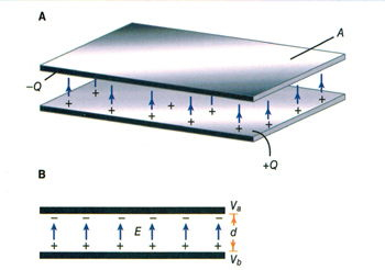
What Is Capacitance?
Capacitance is the ability of a system to store electric charge when voltage is applied across conducting plates separated by a dielectric material. It represents a voltage relationship between stored charge, measured in coulombs, and potential difference, measured in volts. The resulting unit, the farad, defines how many coulombs of charge can be stored per volt applied.
Engineers asking what is capacitance are not seeking a textbook definition but an understanding of how stored electric charge behaves under applied voltage and frequency constraints.
Physically, capacitance increases with greater plate area and decreases as the separation distance grows. The dielectric constant,…
View more

How to Save Electricity?
How to save electricity? Improve energy efficiency, switch to LED lighting, manage standby power, use smart thermostats, insulate homes, schedule heavy appliances off-peak, and conduct energy audits to cut power consumption and lower bills.
How to Save Electricity?
How to Save Electricity is a popular question. It involves energy conservation and lessens real dollars and preserves a public resource. Here are some ways to cut energy costs without compromising your lifestyle too much. For a deeper primer on cutting household consumption, explore this saving electricity guide for actionable steps. Control heating and cooling costsIn some climates, heating and cooling represent…
View more
What is a Watt-hour?
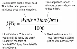
A watt-hour (Wh) is a unit of electrical energy equal to one watt of power used for one hour. It measures the total energy consumed or stored in electrical systems and is commonly used for appliance energy use, battery capacity, and electricity billing.
A watt-hour is calculated by multiplying power in watts by time in hours. This relationship allows energy use to be measured consistently across appliances, batteries, and electrical systems.
A watt-hour does not describe how fast electricity is being used. It describes the total energy consumed over time. This distinction is why watt-hours appear on battery labels, power…
View more
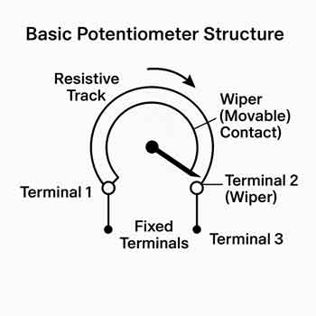
What is a Potentiometer?
A potentiometer is a variable resistor used to control voltage and signal levels in electronic circuits. It adjusts resistance through a movable wiper and is commonly used in audio controls, sensors, dimmers, and calibration applications.
What is a Potentiometer?
What is a potentiometer? A potentiometer is a variable resistor used to control voltage and signal levels in electronic circuits. It adjusts resistance through a movable wiper and is commonly used in audio controls, sensors, dimmers, and calibration applications.
What tends to surprise people new to electronics is how often potentiometers show up in places that feel intuitive rather than…
View more
What is a Watt? Electricity Explained
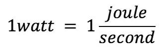
A watt is the SI unit of electrical power that measures the rate at which electrical energy is transferred or consumed.
In electrical systems, power is measured as a rate rather than an accumulated quantity. While a watt measures power at a specific moment, the total amount of energy used over time is typically expressed in kilowatt-hours (kWh), which appear on electricity bills and energy meters. A watt is equivalent to one joule per second, making it a practical unit for relating electrical activity to real-world energy use across devices, circuits, and electrical systems.
Overview: What is a…
View more
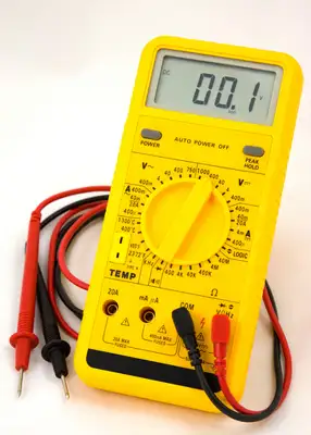
What is a Multimeter?
A multimeter is an electrical testing instrument used to measure voltage, current, and resistance. Essential for electricians, engineers, and hobbyists, this device combines multiple diagnostic tools into a single device for troubleshooting circuits and ensuring safety.
What is a Multimeter?
When something electrical stops working, a multimeter is usually the first tool professionals reach for. It allows you to look inside a circuit, see whether electricity is flowing as it should, and identify faults before they become safety hazards. Used correctly, a multimeter turns invisible electrical behavior into clear, usable information.
Quick answerWhat is a multimeter? An electrical test…
View more
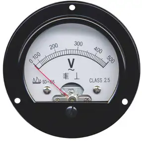
What is a Voltmeter?
What is a voltmeter? A voltmeter is an electrical measuring instrument used to determine voltage across circuit points. Common in electronics, engineering, and power systems, it ensures accuracy, safety, and efficiency when monitoring current and diagnosing electrical performance.
What is a Voltmeter?
Electrical current consists of a flow of charge carriers. Voltage, also known as electromotive force (EMF) or potential difference, manifests as "electrical pressure" that enables current to flow. Given an electric circuit under test with a constant resistance, the current through the circuit varies directly in proportion to the voltage across the circuit. A voltmeter measures potential…
View more

What is Power Factor? Understanding Electrical Efficiency
Power factor describes how efficiently electrical power is used in AC systems by comparing real power to apparent power. It explains reactive power, phase angle, and why a poor power factor (PF) increases losses, demand charges, and equipment stress.
What is Power Factor Explained
In alternating current systems, not all supplied electrical power is converted into useful work. Some energy circulates between the source and the load, supporting magnetic and electric fields without directly producing output. Power factor describes how effectively an electrical system converts supplied electricity into usable energy.
Power Quality Analysis Training
Inductive loads, such as motors…
View more
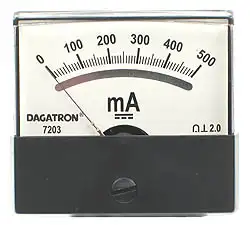
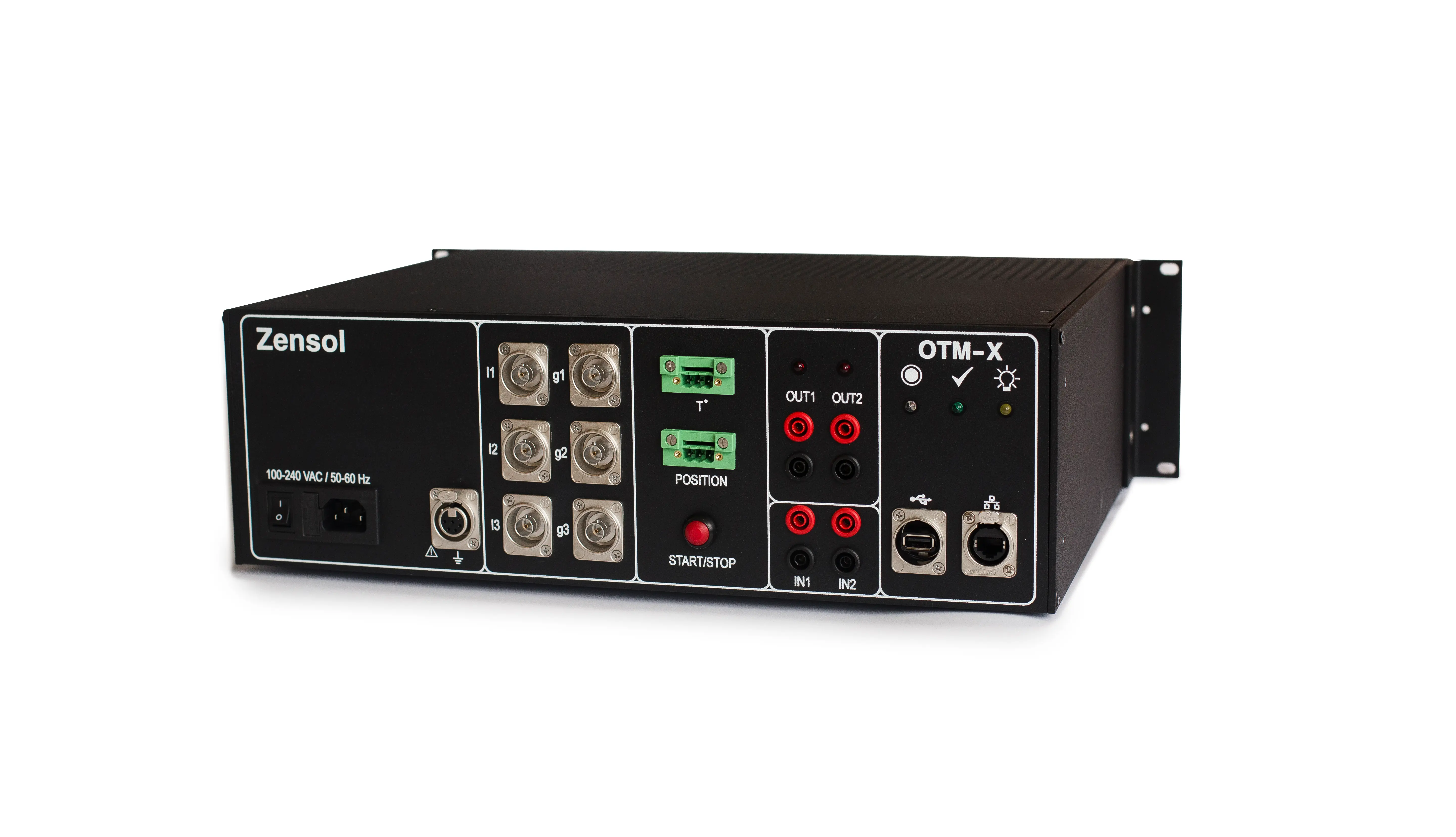
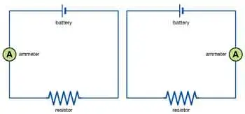
What does an Ammeter Measure?
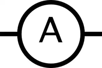
An ammeter measures the electric current flowing through a circuit and displays it in amperes (A). Becoming part of the current path allows technicians and engineers to observe the amount of electrical charge moving through a conductor at any given moment. This measurement is essential for verifying load behavior, identifying abnormal operating conditions, and confirming whether equipment is performing within its intended electrical limits.
How does an Ammeter Measure Current?
An ammeter displays the rate of electric charge flowing through a conductor. Current is measured in amperes, commonly called amps, and the instrument takes its name directly from that…
View more
What is Voltage?
Voltage is the electrical potential difference that drives electric current through a circuit. Measured in volts, it represents energy per unit charge and determines how electrical systems deliver power safely and efficiently.
What is Voltage?
Voltage describes the electrical force that causes a charge to move within a circuit. It represents the difference in electrical potential energy between two points and determines how strongly electrons are pushed through a conductor. Without voltage, electrical charge remains stationary, and no current can exist.
Because voltage cannot be directly observed, it is often explained using analogies. One common analogy is water pressure…
View more