What is Voltage?

By Harold WIlliams, Associate Editor
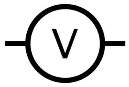

What is Voltage

Voltage is the electrical potential difference between two points, providing the force that moves current through conductors. It expresses energy per charge, powering devices, controlling circuits, and ensuring efficient and safe operation of electrical and electronic systems.


What is Voltage?

Voltage is the electric potential difference, the work done per unit charge (Joules per Coulomb). It: 

✅ Is the difference in electric potential energy between two points in a circuit.

✅ Represents the force that pushes electric current through conductors.

✅ It is measured in volts (V), and it is essential for power distribution and electrical safety.

To comprehend the concept of what is voltage, it is essential to understand its fundamental principles. Analogies make this invisible force easier to picture. One of the most common is the water pressure analogy: just as higher water pressure pushes water through pipes more forcefully, higher voltage pushes electric charges through a circuit. A strong grasp of voltage begins with the fundamentals of electricity fundamentals, which explain how current, resistance, and power interact in circuits.

Another way to imagine what is voltage is as a hill of potential energy. A ball placed at the top of a hill naturally rolls downward under gravity. The steeper the hill, the more energy is available to move the ball. Likewise, a higher voltage means more energy is available per charge to move electrons in a circuit.

A third analogy is the pump in a water system. A pump creates pressure, forcing water to move through pipes. Similarly, a battery or generator functions as an electrical pump, supplying the energy that drives electrons through conductors. Without this push, charges would remain in place and no current would flow.

Together, these analogies—water pressure, potential energy hill, and pump—show how voltage acts as the essential driving force, the “electrical pressure” that enables circuits to function and devices to operate. Since voltage and Current are inseparable, Ohm’s Law shows how resistance influences the flow of electricity in every system.

These analogies help us visualize voltage as pressure or stored energy, but in physics, voltage has a precise definition. It is the work done per unit charge to move an electric charge from one point to another. Mathematically, this is expressed as:

V = W / q

where V is voltage (in volts), W is the work or energy (in joules), and q is the charge (in coulombs). This equation shows that one volt equals one joule of energy per coulomb of charge.

In circuit analysis, voltage is also described through Ohm’s Law, which relates it to current and resistance:

V = I × R

where I is current (in amperes) and R is resistance (in ohms). This simple but powerful formula explains how voltage, current, and resistance interact in every electrical system.

Italian physicist Alessandro Volta played a crucial role in discovering and understanding V. The unit of voltage, the volt (V), is named in his honor. V is measured in volts, and the process of measuring V typically involves a device called a voltmeter. In an electrical circuit, the V difference between two points determines the energy required to move a charge, specifically one coulomb of charge, between those points. The history of voltage is closely tied to the History of Electricity, where discoveries by pioneers like Volta and Franklin have shaped modern science.

An electric potential difference between two points produces an electric field, represented by electric lines of flux (Fig. 1). There is always a pole that is relatively positive, with fewer electrons, and one that is relatively negative, with more electrons. The positive pole does not necessarily have a deficiency of electrons compared with neutral objects, and the negative pole might not have a surplus of electrons compared with neutral objects. But there's always a difference in charge between the two poles. So the negative pole always has more electrons than the positive pole.


Fig 1. Electric lines of flux always exist near poles of electric charge.


The abbreviation for voltage measurement is V. Sometimes, smaller units are used. For example, the millivolt (mV) is equal to a thousandth (0.001) of a volt. The microvolt (uV) is equal to a millionth (0.000001) of a volt. And it is sometimes necessary to use units much larger than one volt. For example, one kilovolt (kV) is equal to one thousand volts (1,000). One megavolt (MV) is equal to one million volts (1,000,000) or one thousand kilovolts. When comparing supply types, the distinction between Direct Current and AC vs DC shows why standardized voltage systems are essential worldwide.

The concept of what is voltage is closely related to electromotive force (EMF), which is the energy source that drives electrons to flow through a circuit. A chemical battery is a common example of a voltage source that generates EMF. The negatively charged electrons in the battery are compelled to move toward the positive terminal, creating an electric current.

In power distribution, three-phase electricity and 3 Phase Power demonstrate how higher voltages improve efficiency and reliability.

Voltage is a fundamental concept in electrical and electronic systems, as it influences the behavior of circuits and devices. One of the most important relationships involving V is Ohm's Law, which describes the connection between voltage, current, and resistance in an electrical circuit. For example, Ohm's Law states that the V across a resistor is equal to the product of the current flowing through it and the resistance of the resistor. 

The voltage dropped across components in a circuit is critical when designing or analyzing electrical systems. Voltage drop occurs when the circuit components, such as resistors, capacitors, and inductors, partially consume the V source's energy. This phenomenon is a crucial aspect of circuit analysis, as it helps determine a system's power distribution and efficiency. Potential energy is defined as the work required to move a unit of charge from different points in an electric dc circuit in a static electric field.  Engineers often analyze Voltage Drop to evaluate circuit performance, alongside concepts like Electrical Resistance.

Voltage levels are standardized in both household and industrial applications to ensure the safe and efficient operation of electrical equipment. In residential settings, common voltage levels range from 110 to 240 volts, depending on the country. Industrial applications often utilize higher voltages, ranging from several kilovolts to tens of kilovolts, to transmit electrical energy over long distances with minimal losses.

Another important distinction in the realm of voltage is the difference between alternating current (AC) and direct current (DC). AC alternates periodically, whereas DC maintains a constant direction. AC is the standard for most household and industrial applications, as it can be easily transformed to different voltage levels and is more efficient for long-distance transmission. DC voltage, on the other hand, is often used in batteries and electronic devices.

Voltage is the driving force behind the flow of charge carriers in electrical circuits. It is essential for understanding the behavior of circuits and the relationship between voltage, current, and resistance, as described by Ohm's Law. The importance of V levels in household and industrial applications, as well as the significance of voltage drop in circuit analysis, cannot be overstated. Finally, the distinction between AC and DC voltage is critical for the safe and efficient operation of electrical systems in various contexts.

By incorporating these concepts into our understanding of voltage, we gain valuable insight into the world of electricity and electronics. From the pioneering work of Alessandro Volta to the modern applications of voltage in our daily lives, it is clear that voltage will continue to play a crucial role in the development and advancement of technology. Foundational principles such as Amperes Law and the Biot Savart Law complement voltage by describing how currents and magnetic fields interact.

Related News

What Is Alternating Current

Alternating current (AC) is a type of electrical flow where the direction of current reverses periodically. Used in most homes and industries, AC is efficient for long-distance transmission and powers devices like motors, lights, and appliances through oscillating voltage.


What is Alternating Current?

Alternating current is a fundamental aspect of electrical systems that have shaped our world in countless ways. Its ability to be easily generated, converted to different voltages, and transmitted over long distances has made it the preferred choice for power transmission and distribution. Additionally, the many advantages of AC, such as compatibility with various devices and safety features, have made it indispensable in our daily lives.

✅ Powers homes, businesses, and industrial equipment through reliable energy transmission.

✅ Changes direction periodically, unlike DC, which flows one way.

✅ Enables long-distance energy delivery with reduced power loss.


To answer the question: What is alternating current? We need to first understand the role of a conductor, which is essential in AC systems, as conductors carry the oscillating electrical energy throughout circuits.


Aspect Description Related Concept
Definition Electric current that periodically reverses direction, forming a sine wave. What is Alternating Current
AC vs. DC AC changes direction; DC flows in one direction only. Difference Between AC and DC
Waveform Typically sinusoidal, but can also be square or triangular. Impedance
Frequency Number of cycles per second (50 Hz or 60 Hz depending on the region). Unit of Electrical Resistance
Voltage Transformation Easily adjusted using transformers for long-distance transmission. Transformer Grounding
Measurement Tools Multimeters and voltmeters measure AC voltage and current. What is a Multimeter, What is a Voltmeter
Key Components Conductors, capacitors, resistors, and inductors are essential to AC systems. What is a Capacitor, What is a Conductor
Generation Principle Based on electromagnetic induction through rotating magnetic fields. Electromagnetic Induction
Common Applications Powering homes, industrial machines, and electrical grids. Electricity Grid
Inventor Nikola Tesla pioneered practical AC power systems and the induction motor. History of Electricity


Understanding AC and DC

In the world of electricity, there are two primary forms of electric current: alternating current (AC) and direct current (DC). Understanding the distinctions between these two types of currents and their applications in daily life is essential to appreciate the advances in electrical engineering and the technology that surrounds us. A multimeter is commonly used to measure AC voltage and current in residential and industrial electrical systems.


AC vs. DC: Basic Differences

AC and DC are two distinct methods by which electric charge is transferred through a circuit. AC involves the flow of charge that periodically reverses direction, creating a waveform typically resembling a sine wave. On the other hand, DC refers to the flow of charge in a single, constant direction. The differences in their nature, functionality, and applications create a contrasting landscape in the electrical power sector. Devices like the voltmeter are specifically designed to measure AC or DC voltage, helping technicians verify circuit functionality and safety.


Why AC Is Preferred for Power Transmission

One key reason why AC is preferred over DC is its ability to easily convert to and from high voltages, making electric power transmission across long distances more efficient. Additionally, transformers can increase or decrease AC voltage, resulting in minimal power loss during long-distance transmission. In contrast, DC power cannot be altered as conveniently, making it less suitable for power transmission over extended distances.


How Alternating Current Works

The working principle of AC is centred around the changing magnetic field created by the flow of electric current. As the current changes direction, the magnetic field also alternates, inducing a voltage in the nearby conductors. This property of AC is fundamental to the operation of AC generators and transformers.

  • AC operation is based on electromagnetic induction

  • Rreversal creates alternating magnetic fields

  • Voltage is induced in nearby conductors


The Role of Nikola Tesla in AC Development

The invention of AC can be attributed to multiple individuals, but the Serbian-American inventor, Nikola Tesla, is often credited with pioneering AC systems. Tesla's work on AC power transmission and his development of the induction motor helped establish AC as the dominant form of electricity.


Frequency: 50 Hz vs. 60 Hz

In frequency, the terms 50-cycle and 60-cycle AC refer to the number of times the current changes direction in one second. The frequency of AC power varies globally, with 50 Hz being the standard in many parts of Europe, Asia, and Africa, while 60 Hz is the norm in North America.

  • 50 Hz is standard in Europe, Asia, and Africa

  • 60 Hz is common in North America

  • Frequency affects compatibility and performance of electrical devices

This difference in frequency can affect the operation of certain appliances and devices, making it essential to use the appropriate frequency for the intended purpose.


Advantages of Alternating Current

The advantages of AC over DC extend beyond efficient power transmission. AC is easier to generate and is widely used for electric power generation, making it more accessible and cost-effective. Moreover, AC systems are safer as they can be easily switched off when required, reducing the risk of electrical accidents. AC is versatile and can power various devices, from small household appliances to large industrial machines.

Key benefits of AC:

  • Easily transformed to higher or lower voltages

  • Safer switching and control in circuits

  • Powers a wide range of residential and industrial devices


How AC Is Generated and Transmitted

The generation and transmission of AC are crucial components of the electrical power infrastructure. AC is generated through various means, such as hydroelectric, thermal, and nuclear power plants, which use generators to convert mechanical energy into electrical energy.

Transmission components:

  • Transformers: Adjust voltage levels

  • Transmission towers: Carry high-voltage lines

  • Substations: Regulate voltage for safe end-use

Once generated, AC is transmitted through power lines that consist of transformers, transmission towers, and substations, which adjust the voltage levels for efficient distribution and usage.


The Role of AC in Daily Life

AC plays a vital role in our daily lives, as it powers most of the appliances and devices we rely on, including lights, computers, and household appliances. In addition, its compatibility with transformers, ease of generation, and ability to transmit power over long distances make it a cornerstone of modern electrical systems.

Frequency has a notable impact on AC usage. In addition to determining the compatibility of devices with a region's power supply, the frequency of AC power affects the speed and performance of electrical motors. A change in frequency may result in the motor operating at a different speed or, in some cases, causing it to malfunction.

Transformers are essential devices in AC systems, as they adjust voltage levels to meet the requirements of various applications. They function by utilizing the principle of electromagnetic induction, where a changing magnetic field in the primary coil induces a voltage in the secondary coil. By adjusting the number of turns in the coils, transformers can efficiently increase or decrease the voltage of AC power, depending on the specific application's needs.

The differences between AC and DC are crucial in understanding the diverse landscape of electrical power. The invention of AC by Nikola Tesla and other inventors has revolutionized the way electricity is generated, transmitted, and utilized. With an appreciation for the characteristics and applications of AC, we can gain a deeper understanding of the technology and infrastructure that powers our world.


How Does Alternating Current Work?

AC works by periodically reversing the direction of the electric charge flow within a circuit. In contrast to DC, which flows in a constant direction, AC oscillates back and forth. This oscillation is typically represented as a waveform, often in the shape of a sine wave. Let's dive deeper into how AC works.

AC is characterized by a waveform that typically takes the shape of a sine wave, allowing for smooth and continuous changes in voltage over time. This makes it ideal for long-distance transmission across the power grid, where electricity generated by a generator must travel efficiently to homes and businesses. The frequency of this current—measured in cycles per second or hertz (Hz)—determines how rapidly the voltage changes direction, impacting device performance and grid efficiency. As current flows through a conductor, it can be stepped up or down using a transformer, enabling voltage levels to be optimized for safe and effective delivery.

Generation: AC is generated using a rotating magnetic field to induce an electric current in a conductor. This is done using devices such as generators and alternators, which convert mechanical energy into electrical energy. In these devices, a coil of wire rotates within a magnetic field, or a magnet rotates around a stationary coil. This rotation causes the magnetic field to interact with the conductor, inducing a voltage and, consequently, an electric current that changes direction periodically.

Waveform: The alternating nature of AC is depicted by a waveform, which shows the voltage or current as a function of time. The most common waveform for AC is the sine wave, which can also take other forms, such as square or triangular waves. The waveform's shape determines the characteristics of the AC and how it interacts with various electrical components.

Frequency: One important parameter of AC is its frequency, which indicates the number of complete cycles the current undergoes per second. It is measured in hertz (Hz). Common frequencies include 50 Hz and 60 Hz, but other frequencies can also be used depending on the application. The frequency of the AC power supply affects the performance and compatibility of devices and equipment connected to it.

Voltage and current relationship: In an AC circuit, the voltage and current can be in phase (i.e., they reach their peak values simultaneously) or out of phase (i.e., they reach their peak values at different times). The phase relationship between voltage and current in an AC circuit can significantly impact power delivery and system efficiency. A voltage sag can disrupt sensitive equipment, making voltage regulation a key part of power quality analysis.

Transformers: A key advantage of AC is that its voltage can be easily changed using transformers. Transformers operate on the principle of electromagnetic induction, where a changing magnetic field in the primary coil induces a voltage in the secondary coil. By adjusting the number of turns in the coils, the transformer can step up or down the AC voltage as needed. This ability to adjust voltage levels makes AC an efficient choice for long-distance power transmission.


Frequently Asked Questions


What is the formula to calculate alternating current?

To calculate the value of AC at any given time, you need to know the current's amplitude (maximum value) and the angular frequency. The general formula for calculating instantaneous current in an AC circuit is:

i(t) = I_max * sin(ωt + φ)

Where:

  • i(t) is the instantaneous current at time t

  • I_max is the amplitude or peak current

  • ω (omega) is the angular frequency, calculated as 2πf (where f is the frequency in hertz)

  • t is the time at which you want to calculate the current

  • φ (phi) is the phase angle, which accounts for any phase shift between the voltage and the current waveforms

Remember that this formula assumes a sinusoidal waveform, the most common form of AC. If the waveform is not sinusoidal, the formula will be different and depend on the specific shape of the waveform.

Another important value for AC circuits is the root-mean-square (RMS) current, which measures the effective value of the current. The RMS current is useful for calculating power in AC circuits and can be compared to the steady current value in DC circuits. The formula to calculate RMS current from the peak current is as follows:

I_RMS = I_max / √2

Where:

  • I_RMS is the root-mean-square current

  • I_max is the amplitude or peak current

  • √2 is the square root of 2, approximately 1.414

  • Using these formulas, you can calculate the instantaneous current value for an alternating current waveform and determine the effective or RMS current value.

To understand how voltage affects electrical circuits, it's essential to examine how voltage drop can lead to energy loss, particularly over long distances.


Related Articles


View more

How Is Electricity Generated?

It is produced by converting various energy sources, such as fossil fuels, nuclear, solar, wind, or hydro, into electrical energy using turbines and generators. These systems harness mechanical or chemical energy and transform it into usable power.


How Is Electricity Generated?

✅ Converts energy sources like coal, gas, wind, or sunlight into power

✅ Uses generators driven by turbines to create electrical current

✅ Supports global power grids and industrial, commercial, and residential use


Understanding Electricity Generation

Electricity generation is the lifeblood of modern civilization, powering homes, industries, hospitals, transportation systems, and digital infrastructure. But behind the flip of a switch lies a vast and complex process that transforms raw energy into electrical power. At its core, electricity is generated by converting various forms of energy—mechanical, thermal, chemical, or radiant—into a flow of electric charge through systems engineered for efficiency and reliability.

Understanding the role of voltage is essential in this process, as it determines the electrical pressure that drives current through circuits.

According to the Energy Information Administration, the United States relies on a diverse mix of technologies to produce electric power, including fossil fuels, nuclear power, and renewables. In recent years, the rapid growth of solar photovoltaic systems and the widespread deployment of wind turbines have significantly increased the share of clean energy in the national grid. These renewable systems often use turbines to generate electricity by converting natural energy sources—sunlight and wind—into mechanical motion and ultimately electrical power. This transition reflects broader efforts to reduce emissions while meeting rising electric power demand.


How Power Generation Works

Most electricity around the world is produced using turbines and generators. These devices are typically housed in large-scale power plants. The process begins with an energy source—such as fossil fuels, nuclear reactions, or renewable inputs like water, wind, or sunlight—which is used to create movement. This movement, in turn, drives a turbine, which spins a shaft connected to a generator. Inside the generator, magnetic fields rotate around conductive coils, inducing a voltage and producing alternating current (AC) electricity. This method, known as electromagnetic induction, is the fundamental mechanism by which nearly all electric power is made.

In designing and maintaining electrical systems, engineers must also consider voltage drop, which can reduce efficiency and power quality. You can evaluate system losses using our interactive voltage drop calculator, and better understand the math behind it using the voltage drop formula.


Energy Sources Used in Power Production

Steam turbines remain the dominant technology in global energy production. These are especially common in plants that burn coal, natural gas, or biomass, or that rely on nuclear fission. In a typical thermal power plant, water is heated to create high-pressure steam, which spins the turbine blades. In nuclear facilities, this steam is generated by the immense heat released when uranium atoms are split. While highly efficient, these systems face environmental and safety concerns—greenhouse gas emissions from fossil fuels, radioactive waste and accident risk from nuclear power.

Power quality in these plants can be impacted by voltage sag, which occurs when systems experience a temporary drop in electrical pressure, often due to sudden large loads or faults. Managing such variations is crucial to stable output.


The Rise of Renewable Energy in Electricity Generation

Alongside these large-scale thermal technologies, renewable sources have grown significantly. Hydroelectric power harnesses the kinetic energy of falling or flowing water, typically from a dam, to spin turbines. Wind energy captures the movement of air through large blades connected to horizontal-axis turbines. Solar power generates electricity in two distinct ways: photovoltaic cells convert sunlight directly into electric power using semiconductors, while solar thermal plants concentrate sunlight to heat fluids and produce steam. Geothermal systems tap into the Earth’s internal heat to generate steam directly or via heat exchangers.

These renewable systems offer major advantages in terms of sustainability and environmental impact. They produce no direct emissions and rely on natural, often abundant energy flows. However, they also face limitations. Solar and wind power are intermittent, meaning their output fluctuates with weather and time of day. Hydropower and geothermal are geographically constrained, only viable in certain regions. Despite these challenges, renewables now account for a growing share of global electricity generation and play a central role in efforts to decarbonize the energy sector.

In areas where water and electricity coexist—such as hydroelectric plants—understanding the risks associated with water and electricity is critical to ensure operational safety and prevent electrocution hazards.


Generators and Turbines: The Heart of Electricity Generation

Generators themselves are marvels of electromechanical engineering. They convert rotational kinetic energy into electrical energy through a system of magnets and copper windings. Their efficiency, durability, and capacity to synchronize with the grid are critical to a stable electric power supply. In large plants, multiple generators operate in parallel, contributing to a vast, interconnected grid that balances supply and demand in real-time.

Turbines, powered by steam, water, gas, or wind, generate the rotational force needed to drive the generator. Their design and performance have a significant impact on the overall efficiency and output of the plant. Measuring output accurately requires devices like a watthour meter or wattmeters, which are standard tools in generation stations.

Technicians often use formulas such as Watt’s Law to determine power consumption and verify performance. Understanding what ammeters measure also plays a role in monitoring electrical current flowing through generator systems.

Related Articles


View more

What is Power Factor? Understanding Electrical Efficiency

Power factor is the ratio of real power to apparent power in an electrical system. It measures how efficiently electrical energy is converted into useful work. A high power factor means less energy loss and better system performance.

What is Power Factor?

It is defined as the ratio of real power (kW), which performs useful work, to apparent power (kVA), which is the total power supplied to the system.

✅ Indicates how efficiently electrical power is used

✅ Reduces energy losses and utility costs

✅ Improves system capacity and voltage regulation

A poor power factor means that some of the supplied power is wasted as reactive power — energy that circulates in the system but does not perform useful work.

Power Quality Analysis Training

Power Factor Training

Request a Free Power Quality Training Quotation

Inductive loads, such as motors and variable speed drives, are a common cause of poor power factor. This inefficiency can lead to higher electric bills, particularly for industrial customers, because utilities often base demand charges on kVA rather than just on kW. To correct a poor power factor, capacitor banks are often installed to offset the inductive reactive power, reducing wasted energy and improving system efficiency.

A poor power factor can lead to higher electricity bills, especially for industrial customers who face demand charges based on kVA. Utilities must supply both the real and reactive components of power, which you can learn more about in our Apparent Power Formula: Definition, Calculation, and Examples guide. To correct power factor issues, capacitor banks are often installed to offset inductive effects and bring the system closer to unity power factor.


Understanding Power Factor in Electrical Systems

Power factor (PF) is not just about efficiency — it also reflects the relationship between voltage and current in an electrical circuit. It measures how closely the voltage waveform and current waveform are aligned, or "in phase," with each other.

  • Leading Power Factor: Occurs when the current waveform leads the voltage waveform. Some lighting systems, like compact fluorescent lamps (CFLs), can produce a leading power factor.

  • Lagging Power Factor: Occurs when the current waveform lags behind the voltage waveform. This is typical in systems with motors and transformers. See our article on Lagging Power Factor and How to Correct It for a detailed discussion.

  • Non-Linear Loads: Loads that distort the current waveform from its original sine wave shape, often due to switching operations within devices. Examples include electric ballasts and switch-mode power supplies used in modern electronics. Their effect on system stability is discussed in our Power Quality and Harmonics Explained guide.

  • Mixed Loads: Most real-world systems have a mix of linear and non-linear loads, which can partially cancel out some harmonic distortions.


Real, Reactive, and Apparent Power

To fully understand power factor, it helps to grasp the three types of electrical power:

  • Real (or Active) Power: The power that performs actual work in the system, expressed in Watts (W).

  • Reactive (or Non-Active) Power: The power stored and released by the system’s inductive or capacitive elements, expressed in Volt-Amperes Reactive (VARs). Explore how it’s calculated in our article on Reactive Power Formula in AC Circuits.

  • Apparent Power: The combined effect of real and reactive power, expressed in Volt-Amperes (VA). Utilities must deliver apparent power to serve all the loads connected to their networks.

The relationship between these three can be visualized as a right triangle, with real power as the base, reactive power as the vertical side, and apparent power as the hypotenuse. If you want to calculate power factor quickly, check out our simple How to Calculate Power Factor guide.


A Simple Analogy: The Horse and the Railroad Car

Imagine a horse pulling a railroad car along uneven tracks. Because the tracks are not perfectly straight, the horse pulls at an angle. The real power is the effort that moves the car forward. The apparent power is the total effort the horse expends. The sideways pull of the horse — effort that does not move the car forward — represents the reactive power.

The angle of the horse’s pull is similar to the phase angle between current and voltage in an electrical system. When the horse pulls closer to straight ahead, less effort is wasted, and the real power approaches the apparent power. In electrical terms, this means the power factor approaches 1.0 — the ideal scenario where almost no energy is wasted. For more real-world examples, we provide further explanations in Power Factor Leading vs. Lagging

The formula for calculating power factor is:

PF = Real Power ÷ Apparent Power

If your facility has poor power factor, adding a Power Factor Correction Capacitor can make a significant difference.


Causes of Low Power Factor

Low PF is caused by inductive loads (such as transformers, electric motors, and high-intensity discharge lighting), which are a major portion of the power consumed in industrial complexes. Unlike resistive loads that create heat by consuming kilowatts, inductive loads require the current to create a magnetic field, and the magnetic field produces the desired work. The total or apparent power required by an inductive device is a composite of the following:

• Real power (measured in kilowatts, kW)

• Reactive power, the nonworking power caused by the magnetizing current, required to operate the device (measured in kilovolts, power kVAR)

Reactive power required by inductive loads increases the amount of apparent power (measured in kilovolts-amps, kVA) in your distribution system. The increase in reactive and apparent power causes the PF to decrease.


Simple How-to: Correcting Power Factor

Correcting a low power factor is typically straightforward and can bring significant benefits to a facility’s energy performance. Here are some common methods:

  • Install Capacitor Banks: Capacitors supply leading reactive power, which offsets the lagging reactive power caused by inductive loads such as motors.

  • Use Synchronous Condensers: These specialized rotating machines can dynamically correct power factor in larger industrial settings.

  • Upgrade Motor Systems: High-efficiency motors and variable frequency drives (VFDs) can reduce reactive power consumption.

  • Perform Regular System Audits: Periodic testing and monitoring can identify changes in power factor over time, allowing for proactive corrections.

Implementing power factor correction measures not only improves energy efficiency but also reduces system losses, stabilizes voltage levels, and extends the lifespan of electrical equipment.


Industries Where Power Factor Correction Matters

Industries that operate heavy machinery, large motors, or lighting banks often struggle with low PF. Facilities interested in monitoring their system health can benefit from tools like a Power Quality Analyzer Explained. Proper correction reduces wasted energy, prevents overheating, and extends the equipment's lifespan.

Power factor management is especially important for utilities and high-demand commercial sites, where poor PF can impact both Quality of Electricity and system reliability.

Some key sectors where maintaining a high power factor is vital include:

  • Manufacturing Plants: Motors, compressors, and welding equipment can cause significant reactive power demands.

  • Data Centers: The large number of servers and cooling systems contributes to power inefficiencies.

  • Hospitals: Medical imaging machines, HVAC systems, and other critical equipment generate substantial electrical loads.

  • Commercial Buildings: Lighting systems, elevators, and HVAC units can result in a low power factor without proper correction.

  • Water Treatment Facilities: Pumps and filtration systems involve extensive motor usage, requiring careful management of power quality.

Improving the power factor in these industries not only reduces utility penalties but also enhances the reliability of critical systems.
 

Frequently Asked Questions

What is a good power factor, and why does it matter?

A power factor (PF) of 1.0 (or 100%) is ideal, indicating that all the power supplied is effectively used for productive work. Utilities typically consider a PF above 0.9 (90%) as acceptable. Maintaining a high PF reduces energy losses, improves voltage stability, and can lower electricity costs by minimizing demand charges.


How does low power factor increase my electricity bill?

When your PF drops below a certain threshold (often 90%), utilities may impose surcharges to compensate for the inefficiencies introduced by reactive power. For instance, BC Hydro applies increasing penalties as PF decreases, with surcharges reaching up to 80% for PFs below 50% . Improving your PF can thus lead to significant cost savings.


What causes a low power factor in electrical systems?

Common causes include:

  • Inductive loads: Equipment like motors and transformers consume reactive power.

  • Underloaded motors: Operating motors below their rated capacity.

  • Non-linear loads: Devices like variable frequency drives and fluorescent lighting can distort current waveforms, leading to a lower PF.


How can I improve my facility's power factor?

Improvement strategies encompass:

  • Installing capacitor banks: These provide reactive power locally, reducing the burden on the supply.

  • Using synchronous condensers: Particularly in large industrial settings, they help adjust PF dynamically.

  • Upgrading equipment: Replacing outdated or inefficient machinery with energy-efficient models.

  • Regular maintenance: Ensuring equipment operates at optimal conditions to prevent PF degradation.


Does power factor correction benefit the environment?

Yes. Enhancing PF reduces the total current drawn from the grid, leading to:

  • Lower energy losses: Less heat generation in conductors.

  • Improved system capacity: Allowing more users to be served without infrastructure upgrades.

  • Reduced greenhouse gas emissions: As overall energy generation needs decrease.


Related Articles


View more

What is a Voltage Regulator?

What is a voltage regulator? A control circuit that stabilizes DC output from AC/DC power supplies using feedback, reference, and PWM; includes linear LDOs and switching buck/boost converters, improving line/load regulation, ripple suppression, efficiency.


What Is a Voltage Regulator?

It keeps voltage steady despite load changes, using linear or switching control to cut ripple, protecting circuits.

✅ Maintains setpoint via reference, error amplifier, feedback loop

✅ Linear LDOs offer low noise; dropout defined by headroom

✅ Switching buck/boost provide high efficiency, EMI needs filtering


What is a voltage regulator, and how does it work?

A voltage regulator is a component of the power supply unit that maintains a constant voltage supply through all operational conditions. Voltage regulators can regulate both AC and DC voltages, ensuring a steady, constant voltage supply. The output voltage is usually lower than the input voltage. The regulator compares the output voltage to a reference voltage and uses the difference to adjust the output voltage. An external voltage source or a circuit within the regulator typically sets the reference voltage. The regulator monitors the output voltage and adjusts it to maintain the reference voltage, which ensures a constant output voltage despite fluctuations in the input voltage or load conditions. For a succinct refresher on fundamentals, review what voltage is and how it is quantified in electrical systems.


Why is voltage regulation important in electronic circuits?

Voltage regulation is essential in electronic circuits because all electronic devices are designed to run at predetermined power ratings, including voltage and current. Therefore, the voltage supply should ideally be constant and steady for the device's proper functioning. Any variation in the voltage supply can lead to device malfunction or even failure. Voltage regulation ensures proper device operation and prevents damage due to voltage fluctuations. Design targets often align with a system's nominal voltage to ensure interoperability and safety margins.


What are the different types of voltage regulators?

They can be classified based on their physical design, active components used, and working principle. For example, linear and switching regulators are the most common classifications of active voltage regulators (that use amplifying components like transistors or op-amps).

Linear regulators use amplifying components like transistors or op-amps to regulate the output voltage. They are simple and reliable but less efficient as they waste excess power as heat. Linear regulators are suitable for low-power applications where efficiency is not a major concern. In many loads the effective behavior of a resistor network shapes the current draw and thermal budget.

Switching regulators, on the other hand, use inductors and capacitors to store and transfer energy, making them more efficient than linear regulators. They are commonly used in battery-powered devices as they consume less power. Switching regulators are more complex than linear regulators and require careful design and layout.

They can also be classified based on their physical design. Voltage regulators used in low-voltage electronic devices are usually integrated circuits. Power distribution centers providing AC power to residential and industrial consumers use more sophisticated and mechanically large voltage regulators that maintain a rated voltage regardless of consumption demands across the area. For context, consumer gadgets often operate within defined low-voltage categories that influence package choice and safety standards.


Can a voltage regulator be used for both AC and DC power sources?

Yes, they can be used for both AC and DC power sources. AC voltage regulators are used in power distribution centers to maintain a constant voltage supply to consumers. DC voltage regulators are used in electronic devices that run on DC power sources, such as batteries or DC power supplies. When selecting between sources, it helps to understand the difference between AC and DC and how each impacts regulation strategy.


What is the difference between a voltage regulator and a voltage stabilizer?

Linear voltage regulators and voltage stabilizers are similar in function as they both regulate the output voltage. However, the main difference between the two is in their working principle. They maintain a constant output voltage by adjusting the voltage as needed to maintain a reference voltage. On the other hand, voltage stabilizers maintain a constant output voltage by using a transformer and voltage regulator ics to stabilize the voltage output.


How do you choose the right one for a specific application?

When choosing one for a specific application, several factors should be considered, including the input voltage range, output voltage range, output current requirements, efficiency, and operating temperature range. During prototyping, verify rails with a calibrated voltmeter to confirm stability under representative loads.

The input voltage range refers to the maximum and minimum input voltages that the regulator can handle. The output voltage range is the range of output voltages that the regulator can provide. The output current requirement refers to the amount of current that the regulator needs to supply to the load. Efficiency is an essential factor as it determines how much power is wasted as heat. Higher efficiency regulators consume less power and generate less heat, which is especially important in battery-powered devices. The operating temperature range is also important as some higher output voltage regulators can operate only within a certain temperature range.

It is crucial to select the appropriate type of regulator for the application. For example, linear regulators are suitable for low-power applications where efficiency is not a major concern while switching regulators are more appropriate for high-power applications that require higher efficiency.

There are various types, including adjustable, boost step-up and buck-boost regulators, and constant output. Adjustable ones allow the user to adjust the output voltage as needed, making them versatile for different duty cycle applications. Boost step-up and buck-boost regulators can increase or decrease the output voltage from the input voltage, making them useful for applications where the input voltage is lower than the required output voltage. Constant output voltage regulators maintain a constant output voltage despite changes in input voltage or load conditions.

In electronic circuits, voltage fluctuations and ripple voltage can be problematic. Voltage fluctuations refer to rapid changes in the voltage level, while ripple voltage refers to the residual AC voltage that remains after rectification. Voltage regulators can help minimize voltage fluctuations and ripple voltage in electronic circuits, ensuring proper device operation. After rectification, understanding what a rectifier does helps explain the origin of ripple and filtering needs.


Related Articles

View more

What is a Capacitor?

A capacitor is an electrical component that stores and releases energy in a circuit. It consists of two conductive plates separated by an insulator and is commonly used for filtering, power conditioning, and energy storage in electronic and electrical systems.


What is a Capacitor?

A capacitor is a key component in electronics and power systems. It temporarily stores electrical energy and is widely used in both AC and DC circuits.

✅ Stores and discharges electrical energy efficiently

✅ Used in filtering, timing, and power factor correction

✅ Found in electronics, motors, and power supplies

It is designed for energy storage and can store electric charges, which can be released when needed. In this article, we will delve into the fundamentals of capacitors, including their functions, types, and applications. To better understand how capacitors support overall system performance, explore our Power Quality overview covering the fundamentals of voltage stability and energy flow.

Power Quality Analysis Training

Power Factor Training

Request a Free Power Quality Training Quotation

A capacitor consists of two metallic plates separated by an insulating material known as the dielectric. The dielectric can be made from various materials, such as mica, paper, or ceramic. When voltage is applied across the plates, positive charges accumulate on one plate, while negative charges accumulate on the opposite plate. The amount of capacitor charge that can be stored depends on several factors, including plate area, plate separation, dielectric material, and voltage ratings. Capacitors are often used in capacitor banks to improve power factor and reduce energy losses in electrical systems.

How does a capacitor work? The primary function of a capacitor in an electronic circuit is to store electrical energy. Capacitors can be used for various purposes, such as filtering, timing, and coupling or decoupling signals. In addition, they play a crucial role in power supplies, ensuring that the output voltage remains stable even when there are fluctuations in the input voltage. Learn how capacitive loads influence circuit behavior and why they require precise capacitor selection for optimal performance.

A capacitor stores energy through the electrostatic field created between its plates. The stored energy can be calculated using the formula E = 0.5 * C * V^2, where E is the stored energy, C is the capacitance, and V is the voltage across the capacitor. Capacitance, measured in Farads, is a measure of a capacitor's ability to store charge. The capacitor voltage rating is crucial for ensuring safe operation and preventing dielectric breakdown during voltage spikes.

So, when I am asked what is a capacitor? I tell readers about several types of capacitors, each with unique applications. Common types include ceramic, electrolytic, film, and tantalum capacitors. Ceramic capacitors are widely used due to their low cost and small size. They are ideal for high-frequency applications and decoupling in power supply circuits. On the other hand, Electrolytic capacitors are popular for their high capacitance values and are commonly used in filtering and energy storage applications. Capacitors play a crucial role in power factor correction, enabling industrial systems to reduce demand charges and enhance energy efficiency.

Dielectric materials used in capacitors can be organic (such as paper) or inorganic (such as ceramic). The choice of dielectric material depends on factors like the desired capacitance value, voltage rating, and operating temperature range. Additionally, different dielectric materials exhibit varying properties, making them suitable for specific applications. For a deeper understanding of energy relationships, see how apparent power differs from real and reactive power in systems using capacitors.

A capacitor can be classified as polarized or non-polarized based on the presence or absence of polarity. Polarized capacitors, like electrolytic capacitors, have a positive and a negative terminal and must be connected correctly in a circuit to function properly. Non-polarized capacitors, like ceramic capacitors, do not have a specific polarity and can be connected in any orientation.

A Capacitor behaves differently in AC and DC voltage circuits. In DC circuits, once a capacitor is charged, it blocks the flow of current, essentially acting as an open circuit. However, in ac voltage circuits, capacitors allow the flow of alternating current. This phenomenon is known as displacement current, which occurs due to the continuous charging and discharging of charges.

So, what is a capacitor? Understanding what a capacitor is and how it works is essential for anyone interested in electronics. The Capacitor plays a vital role in a wide range of applications, from energy storage and filtering to signal coupling and decoupling. Understanding the various types of capacitors and their specific applications enables you to make informed decisions when designing or troubleshooting electronic circuits. Explore how an automatic power factor controller dynamically adjusts capacitor usage to maintain an efficient power factor in real-time.


Related Articles


View more

What is Electric Load

Electric load refers to the amount of electrical power consumed by devices in a system. It determines demand on the power supply and affects energy distribution, efficiency, and system design.


What is Electric Load?

✅ Measures the power consumed by electrical devices or systems

✅ Impacts system design, energy use, and load management

✅ Varies by time, usage patterns, and connected equipment

What is electric load? It refers to the total power demand placed on a circuit by connected devices. Electric load, such as lighting, motors, and appliances, impacts energy use, system sizing, and overall efficiency across residential, commercial, and industrial settings.

An electric load refers to any device or system that consumes electric power to perform work, such as an electric motor, lighting fixture, or household electrical appliances. These loads draw electrical energy from the power source, impacting both system efficiency and capacity planning. Accurate electrical load calculation is crucial for designing circuits, selecting the correct breakers, and ensuring safe operation in homes, businesses, and industrial facilities. Using real-time monitoring tools, engineers can assess load patterns, identify peak demand, and implement energy-saving strategies through smart load management systems.

An electric load can be anything that consumes power, such as lights, appliances, heating systems, motors, and computers. In electrical engineering, a load represents the demand that a device or installation places on the power source.

Electric load is closely influenced by regional consumption patterns, which can be explored in more detail in Electricity Demand in Canada, highlighting how climate and industry shape national power usage.

Different types of types exist, and they are classified based on their characteristics. Resistive loads include, for example, converting energy directly into heat, such as heaters or incandescent light bulbs. Inductive loads, however, require energy to create a magnetic field, such as motors or transformers. Capacitive loads, meanwhile, store and release energy, such as capacitors used in a powered circuit.


An electric load refers to any device or circuit that consumes energy in a system. A common example is a load that consists of appliances such as heaters or ovens, where the primary component is a heating element. This heating element converts energy into heat, providing warmth or cooking power. It consists of a heating mechanism that demands specific amounts of powered energy depending on the device’s power requirements, which is crucial for maintaining an efficient and balanced system. For readers new to electrical concepts, the Basic Electricity Handbook provides foundational knowledge that helps contextualize the meaning of electricity in power systems.


Types of Electrical Loads

Electric loads fall into three primary categories:

  • Resistive: Devices like incandescent light bulbs, heaters, and toasters. These convert energy directly into heat.

  • Inductive: Motors, transformers, and fans. Inductive loads create magnetic fields to operate, often resulting in a lagging power factor.

  • Capacitive: Capacitors are used in power factor correction equipment or some specialized electronic devices. They store energy temporarily.

Each load type interacts differently with the system, impacting both efficiency and stability.

Related: Understand how resistive loads behave in a circuit.


How to Calculate Electric Load

Accurately calculating electric load is important for selecting the correct wire size, circuit breakers, and transformer ratings.


For example:

  • If a device operates at 120 volts and draws 5 amps:

    • Load = 120 × 5 = 600 watts


Step-by-Step Example for a Household Circuit:

  1. Add up the wattage of all devices on the circuit.

  2. Divide the total wattage by the system voltage to find the total current load.

  3. Compare the load to the circuit breaker rating to ensure it is not overloaded.

Tip: Always design for 80% of breaker capacity for safety.


Why Understanding Electric Load Matters

Understanding electric load has real-world implications:

  • Energy Bills: Higher demand results in higher costs, particularly for businesses subject to demand charges.

  • System Design: Correct assessment ensures that wiring, transformers, and protection devices are appropriately sized.

  • Power Quality: Poor management can lead to low power factor, voltage drops, and even system instability.

  • Maintenance Planning: Predictable loads extend the life of equipment and reduce costly downtime.


Management Strategies

Smart load management can improve system efficiency and reduce costs:

  • Peak Shaving: Reducing consumption during periods of high demand.

  • Shifting: Moving heavy loads to off-peak hours.

  • Power Factor Correction: Installing capacitors to improve system efficiency and lower bills.


Electric load is a critical concept in both residential and industrial settings. By understanding the types of calculations used to determine total demand and the practical impacts on energy costs and system design, you can build safer, more efficient systems.

One critical aspect is the power factor. Power factor is the ratio of active power (measured in watts) to apparent power (measured in volt-amperes). In simpler terms, it is the efficiency of energy usage. A low power factor indicates that a device or system consumes energy more than necessary to perform a given task, leading to higher energy costs and increased strain on the power grid. The relationship between load, bill, and motor is especially evident in provincial models, such as Ontario’s Electricity Cost Allocation, which explains how peak demand affects consumer rates.

An electric load is a critical concept in the design and operation of the power grid. Understanding how it is measured, the different types, power factor, management strategies, peak, shedding, and demand response programs are essential for optimizing the use of the grid and ensuring its reliability. By balancing the demand for power with the grid's capacity, we can reduce energy costs, prevent blackouts, and create a more sustainable energy system. Management is a critical component of infrastructure planning, as discussed in the Transmission & Distribution Channel, which examines how levels affect grid design and performance.

In industrial environments, managing efficiently can lead to significant cost savings and operational stability. Explore these strategies in the Industrial Electric Power Channel.


View more

Sign Up for Electricity Forum’s Newsletter

Stay informed with our FREE Newsletter — get the latest news, breakthrough technologies, and expert insights, delivered straight to your inbox.

Electricity Today T&D Magazine Subscribe for FREE

Stay informed with the latest T&D policies and technologies.
  • Timely insights from industry experts
  • Practical solutions T&D engineers
  • Free access to every issue

Download the 2025 Electrical Training Catalog

Explore 50+ live, expert-led electrical training courses –

  • Interactive
  • Flexible
  • CEU-cerified