What is a Capacitor?

By R.W. Hurst, Editor


What is a Capacitor explained

A capacitor is an electrical component that stores and releases energy in a circuit. It consists of two conductive plates separated by an insulator and is commonly used for filtering, power conditioning, and energy storage in electronic and electrical systems.


What is a Capacitor?

A capacitor is a key component in electronics and power systems. It temporarily stores electrical energy and is widely used in both AC and DC circuits.

✅ Stores and discharges electrical energy efficiently

✅ Used in filtering, timing, and power factor correction

✅ Found in electronics, motors, and power supplies

It is designed for energy storage and can store electric charges, which can be released when needed. In this article, we will delve into the fundamentals of capacitors, including their functions, types, and applications. To better understand how capacitors support overall system performance, explore our Power Quality overview covering the fundamentals of voltage stability and energy flow.

Power Quality Analysis Training

Power Factor Training

Request a Free Power Quality Training Quotation

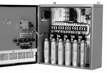
A capacitor consists of two metallic plates separated by an insulating material known as the dielectric. The dielectric can be made from various materials, such as mica, paper, or ceramic. When voltage is applied across the plates, positive charges accumulate on one plate, while negative charges accumulate on the opposite plate. The amount of capacitor charge that can be stored depends on several factors, including plate area, plate separation, dielectric material, and voltage ratings. Capacitors are often used in capacitor banks to improve power factor and reduce energy losses in electrical systems.

How does a capacitor work? The primary function of a capacitor in an electronic circuit is to store electrical energy. Capacitors can be used for various purposes, such as filtering, timing, and coupling or decoupling signals. In addition, they play a crucial role in power supplies, ensuring that the output voltage remains stable even when there are fluctuations in the input voltage. Learn how capacitive loads influence circuit behavior and why they require precise capacitor selection for optimal performance.

A capacitor stores energy through the electrostatic field created between its plates. The stored energy can be calculated using the formula E = 0.5 * C * V^2, where E is the stored energy, C is the capacitance, and V is the voltage across the capacitor. Capacitance, measured in Farads, is a measure of a capacitor's ability to store charge. The capacitor voltage rating is crucial for ensuring safe operation and preventing dielectric breakdown during voltage spikes.

So, when I am asked what is a capacitor? I tell readers about several types of capacitors, each with unique applications. Common types include ceramic, electrolytic, film, and tantalum capacitors. Ceramic capacitors are widely used due to their low cost and small size. They are ideal for high-frequency applications and decoupling in power supply circuits. On the other hand, Electrolytic capacitors are popular for their high capacitance values and are commonly used in filtering and energy storage applications. Capacitors play a crucial role in power factor correction, enabling industrial systems to reduce demand charges and enhance energy efficiency.

Dielectric materials used in capacitors can be organic (such as paper) or inorganic (such as ceramic). The choice of dielectric material depends on factors like the desired capacitance value, voltage rating, and operating temperature range. Additionally, different dielectric materials exhibit varying properties, making them suitable for specific applications. For a deeper understanding of energy relationships, see how apparent power differs from real and reactive power in systems using capacitors.

A capacitor can be classified as polarized or non-polarized based on the presence or absence of polarity. Polarized capacitors, like electrolytic capacitors, have a positive and a negative terminal and must be connected correctly in a circuit to function properly. Non-polarized capacitors, like ceramic capacitors, do not have a specific polarity and can be connected in any orientation.

A Capacitor behaves differently in AC and DC voltage circuits. In DC circuits, once a capacitor is charged, it blocks the flow of current, essentially acting as an open circuit. However, in ac voltage circuits, capacitors allow the flow of alternating current. This phenomenon is known as displacement current, which occurs due to the continuous charging and discharging of charges.

So, what is a capacitor? Understanding what a capacitor is and how it works is essential for anyone interested in electronics. The Capacitor plays a vital role in a wide range of applications, from energy storage and filtering to signal coupling and decoupling. Understanding the various types of capacitors and their specific applications enables you to make informed decisions when designing or troubleshooting electronic circuits. Explore how an automatic power factor controller dynamically adjusts capacitor usage to maintain an efficient power factor in real-time.


Related Articles


Related News

What is a Conductor?

A conductor is a material that allows electric current to flow easily due to its low resistance. Common conductors include copper and aluminum, used in electrical wiring and components. Conductors play a critical role in power distribution and circuit functionality.


What is a Conductor?

A conductor enables the flow of electricity or heat with minimal resistance. It's essential in electrical systems.

✅ Transfers electricity efficiently, commonly using copper or aluminum

✅ Used in wiring, power grids, and electronics

✅ Minimizes resistance for stable current flow

Understanding what a conductor is and how it functions is crucial to comprehending various aspects of modern life, including electricity, thermal management, and electronics. Conductors facilitate the flow of electrons and heat in various applications, while insulators impede these movements. Due to their unique properties and availability, copper, silver, and aluminum are good conductors of electricity. As a result, they are among the most commonly used conductor materials because they facilitate the flow of electricity. Factors affecting conductivity include atomic structure, temperature, and the purity of the material.

Conductors are an integral part of our daily lives, enabling the functioning of various devices and systems we depend on, such as electrical wiring and electronic devices. In contrast, thermal conductors facilitate heat transfer in numerous applications, from car engines to cookware. In addition, the unique category of semiconductors demonstrates that a material can possess both conductive and insulating properties, paving the way for the development of advanced technologies such as transistors and solar cells.


The Role of Conductors in Electricity

A conductor plays an essential role in the world of electricity. It enables the movement of electrons within a material, allowing electrical charge to flow smoothly through an electrical circuit. Electrical conductors consist of atoms that have loosely bound electrons, which are free to move and generate a current when an electric field is applied. This phenomenon is the basis for the flow of electrons in many electrical devices and systems.


Conductors and Insulators: The Key Differences

The primary difference between conductors and insulators lies in their ability to conduct electricity. While conductors, which are solid in nature, allow the flow of electrons, insulators impede this flow due to their tightly bound electrons. Consequently, insulators prevent electric shock or maintain electrical charge within specific boundaries. Good insulators include rubber, plastic, and glass.


Common Conductor Materials

The most commonly used materials for electrical conductors include copper, silver, and aluminum. Copper conductors are often preferred due to their excellent conductivity, relatively low cost, and high availability. Silver possesses the highest conductivity but is more expensive and less abundant. Aluminum is lightweight and affordable, making it an attractive choice for various applications such as power lines.


Factors Affecting Conductivity

The conductivity of a material depends on several factors, including its atomic structure, temperature, and purity. Materials with more free electrons or a regular atomic arrangement are more conducive. Temperature can also influence conductivity, as higher temperatures may cause the atoms in a material to vibrate more, leading to increased resistance. Purity is another essential factor, as impurities can impede the flow of electrons, reducing conductivity.


Applications of Conductors in Everyday Life

Conductors play a vital role in our daily lives, providing the foundation for many devices and systems that rely on the movement of electrons. Some notable examples include electrical wiring, power lines, and electronic devices such as computers and smartphones. Additionally, conductors are used in protective gear like fire-resistant clothing, which incorporates metal fibers to dissipate heat from the body.


Thermal Conductors: Function and Use

Thermal conductors allow heat to flow through them, effectively conducting heat from one area to another. This process is essential in many applications, such as in car engines, where conductors help dissipate heat away from the engine to prevent overheating. Thermal conductors are also found in household items, such as pots and pans, where heat must be transferred evenly for efficient cooking.


Can a Material be Both a Conductor and an Insulator?

In some cases, the material can exhibit both conductive and insulating properties. These materials are known as semiconductors, which possess a conductivity level between conductors and insulators. Silicon and germanium are two common examples of semiconductors. Semiconductors have numerous applications in electronic devices, including transistors and solar cells, which can regulate electrical current and convert sunlight into electricity.

As our understanding of conductors and their properties expands, we anticipate further innovations and improvements in the materials used in these essential components. For example, new conductor materials and composites could potentially be developed, offering better performance, higher efficiency, or enhanced durability. These advancements will contribute to the creation of even more sophisticated technologies and further enhance the quality of our everyday lives.


Related Articles


View more

What is a Busbar?

A busbar is a metallic strip or bar used in electrical systems to conduct electricity within switchgear, distribution panels, and substations. It distributes power efficiently and reduces resistance, enhancing safety and electrical performance.


What is a Busbar?

A busbar is a crucial electrical component used to conduct, distribute, and manage power in electrical systems. Found in commercial, industrial, and utility applications, it helps centralize connections and minimize wiring complexity.

✅ Provides efficient power distribution in electrical panels and substations

✅ Reduces resistance and improves system reliability

✅ Supports compact, organized electrical design for switchgear and distribution boards

A Busbar is an important component of electrical distribution systems, providing a central location for power to be distributed to multiple devices. It is an electrical conductor responsible for collecting electrical power from incoming feeders and distributing it to outgoing feeders. They are made of metal bars or metallic strips and have a large surface area to handle high currents.

How Does it Work?

It is a strip or bar made of copper, aluminum, or another conductive metal used to distribute electrical power in electrical systems. They have a large surface area to handle high currents, which reduces the current density and minimizes losses. They can be insulated or non-insulated, and they can be supported on insulators or wrapped in insulation. They are protected from accidental contact by either a metal earthed enclosure or elevation out of normal reach.

They collect electrical power from incoming feeders and distribute it to outgoing feeders. The bus bar system provides a common electrical junction for various types of electrical equipment, designed to handle high currents with minimal losses. They are often used in industrial applications, where they are installed in electrical panels or switchgear panels.


Different Types of Busbars

Different types of busbars are available on the market, including those made of copper or aluminum, as well as insulated or non-insulated, and segmented or solid busbars. Copper or brass busbars are used in low-voltage applications, while aluminum busbars are used in high-voltage applications. Insulated busbars are used in situations where accidental contact can occur, and segmented busbars are used to connect different types of equipment.

Busbars can also be classified based on their cross-section. A rectangular is the most common type and is often used in low-voltage applications. On the other hand, a tubular busbar is a hollow cylinder used in high-voltage applications. Finally, a circular one has a circular cross-section and is used in high-current applications.


Busbar Types and Characteristics

Attribute Copper Busbar Aluminum Busbar Laminated Busbar
Conductivity Excellent (≈100% IACS) Good (≈61% IACS) Varies (depends on internal conductor materials)
Weight Heavy Lightweight Moderate
Cost Higher Lower Higher (due to fabrication complexity)
Heat Dissipation Excellent Good Excellent (designed to reduce hot spots)
Applications Switchgear, substations, panels Bus ducts, high-rise buildings Compact power modules, UPS, power electronics
Mechanical Strength High Moderate Moderate to High
Corrosion Resistance High (especially tinned copper) Requires anodizing/coating Depends on encapsulation
Ease of Fabrication Good Excellent Complex


The Purpose of a Busbar in an Electrical System

The primary purpose of an electrical system is to distribute electrical power to different parts of the system. The busbar system collects electrical power from incoming feeders and distributes it to outgoing feeders. Busbars also provide a common electrical junction for different types of electrical equipment.


Busbar and Circuit Breakers

They are often used in conjunction with circuit breakers. Circuit breakers protect electrical circuits from damage caused by overload or short circuits. Additionally, they can be used to isolate the electrical supply in the event of a fault or overload. Circuit breakers are often installed in electrical or switchgear panels, which can be easily accessed and maintained.


Busbars and Electrical Distribution Equipment

They are an essential component of electrical distribution equipment, including electrical panels, switchgear panels, and distribution boards. Electrical panels distribute power to various parts of a building, while switchgear panels control the flow of electrical power in industrial applications. Distribution boards divide the electrical supply into separate circuits at a single location.


Busbar Installation

Installing a busbar involves several basic steps. First, the busbar system's design must be created, considering both the electrical load and the required current-carrying capacity. Then, it is installed in the electrical panel or switchgear panel. Finally, it is connected to the electrical equipment using either bolts, clamps, or welding.


Maintenance

Maintaining a busbar system involves regular inspections and cleaning. The system should be inspected for any damage or corrosion, and the connections should be tightened if they become loose. Regular cleaning of the system is also essential to prevent the buildup of dust or dirt, which can lead to a short circuit.


Safety Precautions

Working with busbars involves high voltage and current, so taking proper safety precautions is essential. The system must be isolated from the electrical system before any maintenance is performed. Personal protective equipment, such as gloves and safety glasses, should be worn while working with busbars. Working on a live system should only be done by trained personnel after ensuring that all necessary safety precautions are in place.


Accidents involving Busbars

Accidents can occur when working with busbars, and they can be dangerous if proper safety precautions are not taken. One common accident that can occur involves accidental contact with a live one. This can cause electrical shock, burns, and even death. Another accident involves short circuits, which can lead to equipment damage, fire, or explosions. These accidents can be prevented by following proper safety procedures and wearing personal protective equipment.

Arc flash accidents, including busbars, are a potential hazard when working with electrical equipment. An arc flash is an electrical explosion that can occur when a fault occurs in an electrical circuit, resulting in a short circuit or electrical discharge. Arc flash accidents can cause severe burns, hearing loss, and even death.

They can be a source of arc flash accidents if proper safety precautions are not taken. For example, if a live busbar comes into contact with an object, it can cause an arc flash. Proper insulation and guarding are necessary to prevent arc flash accidents involving busbars. They should also be installed in a way that minimizes the possibility of accidental contact.

Additionally, they should be designed to handle the expected current load, as overloading can lead to a fault and an arc flash. It is also essential to follow proper maintenance procedures, including regular system inspections and cleaning, to prevent damage or corrosion that can cause faults and arc flashes.

Overall, busbars are related to arc flash accidents as they can be a source of electrical faults that can lead to an arc flash. Therefore, following proper safety procedures, including proper insulation, guarding, and system maintenance, is crucial to prevent arc flash accidents.


Related Articles


View more

Capacitance Definition

Capacitance definition clarifies how a capacitor stores electric charge per unit voltage, measured in farads, influenced by plate area and dielectric, shaping reactance, energy storage, and signal behavior in AC and DC circuits.


What Is the Capacitance Definition?

Capacitance is a component's ability to store electric charge per unit voltage, measured in farads.

✅ Measured in farads with C = Q/V

✅ Depends on plate area, spacing, and dielectric

✅ Affects reactance, filtering, and energy storage


Capacitance Definition

Another important property in AC electronic circuits, besides resistance and inductance, is capacitance. Capacitance is measured in units. The unit of capacitance is the farad. While inductance is represented in a circuit by a coil, capacitance is represented by a capacitor. In its most basic form, the capacitor is constructed of two parallel plates separated by a nonconductor, called a dielectric. In an electrical circuit, a capacitor serves as a reservoir or storehouse for electricity. For a clear overview of device construction and function, see what is a capacitor to relate these fundamentals.


Capacitance Definition in Direct Current

When a capacitor is connected across a source of direct current, such as a storage battery in the circuit shown in Figure 1A, and the switch is then closed, the plate marked B becomes positively charged, and the A plate negatively charged. Current flows in the external circuit when the electrons move from B to A. The current flow in the circuit is at a maximum when the switch is closed, but it continually decreases until it reaches zero. The current becomes zero as soon as the difference in voltage of A and B becomes the same as the applied voltages of the battery. The plates remain charged if the switch is opened, as shown in Figure 1B. Once the capacitor is shorted, it will discharge quickly as shown in Figure 1C. It should be clear that when the capacitor is being charged or discharged, there is current in the circuit, even though the gap between the capacitor plates breaks the circuit. Current is present only during the time of charge and discharge, which is usually short. A broader introduction is provided in what is capacitance for context on this charging behavior.


Fig 1 - Capacitance Definition in direct current.

The RC Time Constant The time required for a capacitor to attain a full electrical charge is proportional to the capacitance and the resistance of the circuit. The resistance of the circuit introduces the element of time into the charging and discharging of a capacitor. When designing filters or timing networks, combining devices affects total C, and capacitance in parallel explains how values add.

When a capacitior charges or discharges through a resistance, a certain amount of time is required for a full charge or discharge. The voltage across the capacitor will not change instantaneously. The rate of charging or discharging is determined by the circuit's time constant. The time constant of a series RC (resistor/ capacitor) circuit is a time interval that equals the product of the resistance in ohms and the capacitance in farad and is symbolized by the greek letter tau (τ). For a concise refresher on definitions and symbols, see capacitance before applying the time constant formula.

τ = RC

The time in the formula is required to charge to 63% of the voltage of the source. The time needed to bring the amount of charge to about 99% of the source voltage is approximately 5 τ. Figure 2 illustrates this relationship of the time constant characteristics of charging. In network calculations, series combinations behave differently, and capacitance in series outlines the reciprocal method used.


Fig 2 - Capacitance Definition discharge curve.

When asked for a capacitance definition, I often explain that capacitance is the measure of a capacitor’s ability to store electric charge. The symbol used for capacitance is the letter C. You can measure the electric potential of the dielectric material in an electronic component where it may store energy. For details on nomenclature and SI units, consult the unit of capacitance and confirm typical values.

As can be seen from the time constant illustration, there can be no continuous movement of direct current through a capacitor. A good capacitor will block
direct current and will pass the effects of pulsing DC or alternating current. For application examples across power supplies, signal coupling, and filtering, explore capacitors to see practical implementations.


Related Articles

View more

What is a Ground Fault? Hazard Explained

A ground fault occurs when electrical current unintentionally flows to the ground, often through a person or conductive surface. It poses serious shock and fire hazards and typically results from damaged wiring, insulation failure, or water intrusion in electrical systems.


What is a Ground Fault?

A ground fault is a potentially hazardous electrical event when an unintended electrical path forms between a live electrical conductor and a grounded surface.

✅ Occurs when electrical current flows to ground through an unintended path

✅ Commonly caused by damaged wires, insulation failure, or moisture

✅ Increases the risk of electrical shock and equipment failure

The flow of current through this unintended path, also known as earth leakage, can cause serious electrical shock hazards and damage to electrical systems. Let's examine the causes, dangers, and preventive measures associated with ground faults. Proper electrical grounding is essential to prevent ground faults, as it ensures that stray currents are safely diverted into the earth. 

There are common causes of ground faults. A ground fault occurs because of several factors, including damaged insulation, incorrect wiring, or moisture in the electrical system. Damaged insulation, for example, can expose the conductor of electricity, allowing it to come into contact with a grounded surface. Additionally, moisture can create a conductive path between live conductors and the earth, thereby increasing the risk. Moisture intrusion and damaged insulation can cause faults similar to arc faults, which are discussed further in our power quality troubleshooting resource.

One of the primary dangers associated with ground faults is the risk of electrical shock. When one occurs, it can create a path to the earth through a person, leading to serious injury or even death. Additionally, they can cause overheating, sparking, and fires in electrical systems, posing a significant risk to property and life.

Ground fault circuit interrupters (GFCIs) are essential devices designed to mitigate the risks associated with ground faults. GFCIs constantly monitor the flow of electrical current between the hot wire and the neutral wire. If an imbalance is detected, the GFCI quickly cuts power to the electrical circuit, preventing electrical shock and minimizing potential damage. GFCI outlets are commonly installed in areas where water is present, such as kitchens, bathrooms, and outdoor spaces, as these locations have a higher risk of ground faults. A grounding system should be regularly inspected to minimize the risk of fire and shock caused by unintentional current paths.


Preventing Ground Faults

Preventing and minimizing ground faults involves several steps. First, proper electrical grounding is critical in reducing the risk. A grounding wire connected to the electrical box creates a path for fault current to flow safely to the earth, reducing the likelihood of electrical shock. Regular inspection and maintenance of electrical systems can also help identify potential issues, such as damaged insulation or incorrect wiring, before they lead to ground faults. Additionally, using GFCI-protected outlets and circuit breakers in high-risk areas can help prevent ground faults and protect against shock hazards.

Understanding the differences between ground faults, short circuits, and arc faults is important, as they are all distinct electrical events with unique risks and causes. A short circuit occurs when a live conductor comes into contact with a neutral or grounded conductor, resulting in a sudden surge of current. This can lead to overheating, fires, or damage to electrical equipment. On the other hand, arc faults occur when an electrical arc forms between conductors, often due to damaged or frayed wiring. Arc faults can generate excessive heat and pose a fire risk.

Identifying one in an electrical system can be accomplished through visual inspection, testing, or the use of specialized equipment. For example, signs of a ground fault may include tripped GFCI outlets or circuit breakers, flickering lights, or a burning smell near electrical equipment. Additionally, testing outlets with a ground fault circuit interrupter tester or a multimeter can help determine if a ground fault is present.

Grounding is crucial in preventing ground faults and protecting against electrical shock. By providing a safe path for fault current to flow, earthing helps minimize the risk of injury and damage to electrical systems. Proper earthing involves connecting all electrical equipment, including outlets, switches, and metal boxes, to a grounding wire connected to the earth. This connection helps ensure that unintended electrical paths, such as those caused by ground faults, are safely grounded.


Understanding Ground Faults

Understanding what a ground fault is and how to prevent it is essential for ensuring electrical safety in residential and commercial settings. Proper earthing, regular inspection and maintenance of electrical systems, and the use of GFCI-protected outlets and circuit breakers are all crucial measures in reducing the risk of electrical hazards. By being aware of the dangers associated with ground faults and taking proactive steps to address them, we can help protect our homes, businesses, and loved ones from electrical hazards.

In addition to the precautions mentioned above, it's essential to exercise caution when using power tools and appliances. Many incidents occur when using power tools in damp environments. Always ensure that power tools are in good working condition, with no frayed cords or damaged insulation. Use GFCI-protected outlets or extension cords when operating them in potentially hazardous conditions.

Moreover, educating yourself and those around you about electrical safety is crucial. Understanding the risks associated with ground faults and knowing how to respond in an electrical emergency can save lives. Regularly reviewing safety procedures and ensuring that everyone in your home or workplace knows how to use GFCI outlets and reset buttons. Circuit breakers can significantly reduce the risk of injury or property damage.

Finally, don't hesitate to consult a licensed electrician if you suspect or encounter any electrical issues. Professional electricians have the knowledge and tools to diagnose and repair electrical problems safely and effectively. Attempting to resolve electrical issues without proper training can be dangerous and may lead to further complications.

By adopting a comprehensive approach to electrical safety, we can minimize risks and create a safer environment for ourselves and our communities. Awareness, preventive measures, and education are crucial in reducing the incidence of injuries and ensuring the well-being of everyone interacting with electrical systems.


Related Articles


View more

What is Capacitance?

Capacitance is the ability of a component to store electrical charge between plates separated by insulation, measured in farads. It is vital in circuits, electronics, and energy storage for voltage regulation, stability, and efficient power system performance.


What is Capacitance?

Capacitance is a fundamental concept in electrical engineering and physics, describing a system's ability to store energy in the form of an electrical charge.

✅ Measures the ability to store electric charge in a circuit

✅ Essential in filtering, timing, and power conditioning

✅ Found in capacitors used in electronics, motors, and power supplies

Capacitance (C = Q / V) measures the amount of electric charge (Q) a system stores per volt (V); unit: farad (F).

Power Quality Analysis Training

Power Factor Training

Request a Free Power Quality Training Quotation

Capacitance is the property of a system that allows it to store electric charge when a voltage, or electric potential difference, is applied across its terminals. This stored charge represents the system’s charge storage capacity, which is directly proportional to the capacitance value and the applied voltage. In alternating current (AC) circuits, capacitors do not pass current in the same way resistors do; instead, they oppose changes in voltage through a phenomenon known as capacitive reactance. This reactance decreases as the frequency of the AC signal increases, making capacitors essential in filtering, tuning, and timing applications. To understand how stored charge behaves across voltage differences, refer to our guide on capacitive load, which explores how capacitors affect AC circuits. For a detailed breakdown of how capacitance is measured, check out the unit of capacitance to understand farads and their practical conversions.


What Determines Capacitance?

The capacitance of a capacitor is determined by its geometry and the properties of the dielectric material between the conductive plates. The unit of capacitance is the farad, which can be measured in farads. Capacitors are often rated in microfarads (μF) or picofarads (pF), depending on their size and intended use.  For the basics of components that store electrical energy, see what is a capacitor to learn how these devices function and their role in circuits.

Learn how stored charge relates to apparent and real power in AC systems by visiting our apparent power vs real power comparison.

When a capacitor is connected to a voltage source, it charges, storing energy as an electrical field between its conductive plates. The amount of energy stored in a capacitor is proportional to its capacitance and the square of the voltage across it. When the voltage source is removed, the capacitor will slowly discharge, releasing the stored energy as an electrical current. Capacitance is also central to power factor optimization—discover how this works with an automatic power factor controller.


RC Circuits: The Role of Capacitance in Charging

A capacitor's charging and discharging behaviour is determined by its capacitance and the properties of the surrounding circuit. For example, in a simple circuit with a resistor and a capacitor, the capacitor will charge up rapidly when first connected to a voltage source. Still, it will then discharge slowly over time as the energy stored in the capacitor is dissipated through the resistor. The time constant of the circuit, which describes the rate at which the capacitor charges and discharges, is determined by the product of the resistance and capacitance of the circuit.

Capacitors are used in various electronic applications, from filtering noise in power supplies to storing energy in flash memory. The capacitance of a capacitor can be tuned by selecting different dielectric materials, changing the geometry of the conductive plates, or adding additional plates in parallel. To explore how capacitors behave when connected end-to-end, visit capacitance in series, which explains the reciprocal formula and voltage behavior.


Dielectric Materials and Their Effect on Capacitance

Dielectric materials are crucial to the operation of capacitors, as they serve as insulators between the conductive plates. The dielectric constant of a material describes its ability to store electrical energy and is a key parameter in determining the capacitance of a capacitor. Dielectric materials can be solid, such as ceramics or plastics, or liquid, such as electrolytes.

Capacitors can store energy in various forms, from high-voltage electrical energy in power supplies to low-voltage electrical energy in portable electronic devices. The energy stored in a capacitor can provide a quick burst of power to a circuit or smooth out variations in a power supply. If you're curious about how capacitors add their values in parallel, the capacitance in parallel page illustrates how capacitances sum directly, enhancing energy storage.


How Capacitance Compares to Resistance and Inductance

Resistance slows down the transfer rate of charge carriers (usually electrons) by "brute force." In this process, some energy is invariably converted from electrical form to heat. Resistance is said to consume power for this reason. Resistance is pre­sent in DC as well as in AC circuits and works the same way for either direct or alternat­ing current. Capacitor performance depends on safe voltage levels; our page on capacitor voltage rating explains these limits in detail.

Inductance impedes the flow of AC charge carriers by temporarily storing the en­ergy as a magnetic field. However, this energy is eventually replenished. For high-capacitance setups in electrical systems, see how banks of capacitors are configured in our capacitor bank overview.

Capacitance impedes the flow of AC charge carriers by temporarily storing the energy as an electric potential field. This energy is given back later, just as it is in an inductor. Capacitance is not generally necessary in pure-DC cir­cuits. However, it can have significance in circuits where DC is pulsating and not steady. If you're studying how capacitance affects reactive energy, visit our breakdown of reactive power formula in electrical circuits.


Capacitance in AC Circuits and Frequency Response

Capacitance, like inductance, can appear unexpectedly or unintentionally. As with inductance, this effect becomes more evident as the ac frequency increases.

Capacitance in electric circuits is deliberately introduced by a device called a capacitor. It was discovered by the Prussian scientist Ewald Georg von Kleist in 1745 and independently by the Dutch physicist Pieter van Musschenbroek at about the same time while investigating electrostatic phenomena. They discovered that electricity generated by an electrostatic machine could be stored for a period and then released. The device, which came to be known as the Leyden jar, consisted of a stoppered glass vial or jar filled with water, with a nail piercing the stopper and dipping into the water. By holding the jar in hand and touching the nail to the conductor of an electrostatic machine, they found that a shock could be obtained from the nail after disconnecting it by touching it with the free hand.

This reaction showed that some of the electricity from the machine had been stored. A simple but fundamental step in the evolution of the capacitor was taken by the English astronomer John Bevis in 1747 when he replaced the water with metal foil, forming a lining on the inside surface of the glass and another covering the outside surface. The interaction of capacitance and system reactance is a key part of understanding power quality, as explained on our reactor reactance in power systems page.


A Visual Thought Experiment: Capacitance Between Metal Plates

Imagine two very large, flat sheets of metal, such as copper or aluminum, that are ex­cellent electrical conductors. Suppose they are each the size of the state of Nebraska and are placed one on top of the other, separated by just a foot of space. What will happen if these two sheets of metal are connected to the terminals of a battery, as shown in Fig. 11-1?


Fig. 11-1. Two plates will become charged electrically, one positively and the other nega­tively.


The two plates will become charged electrically, one positively and the other nega­tively. You might think this would take a little while because the sheets are so big. However, this is a reasonable assumption.

If the plates were small, they would both become charged almost instantly, attaining a relative voltage equal to the battery's voltage. But because the plates are gigantic, it will take a while for the negative one to "fill up" with electrons, and it will take an equal amount of time for the other one to get electrons "sucked out." Finally, however, the volt­age between the two plates will be equal to the battery voltage, and an electric field will exist in the space between the plates.

This electric field will be small at first; the plates don't charge immediately. However, the negative charge and the positive charge will increase over time, depending on the size of the plates and the distance between them. Figure 11-2 is a relative graph showing the in­tensity of the electric field between the plates as a function of time elapsed since the plates are connected to the battery terminals.


Fig. 11-2. Relative electric field intensity, as a function of time, between two metal plates connected to a voltage source. 


Related Articles


View more

What is Power Factor? Understanding Electrical Efficiency

Power factor is the ratio of real power to apparent power in an electrical system. It measures how efficiently electrical energy is converted into useful work. A high power factor means less energy loss and better system performance.

What is Power Factor?

It is defined as the ratio of real power (kW), which performs useful work, to apparent power (kVA), which is the total power supplied to the system.

✅ Indicates how efficiently electrical power is used

✅ Reduces energy losses and utility costs

✅ Improves system capacity and voltage regulation

A poor power factor means that some of the supplied power is wasted as reactive power — energy that circulates in the system but does not perform useful work.

Power Quality Analysis Training

Power Factor Training

Request a Free Power Quality Training Quotation

Inductive loads, such as motors and variable speed drives, are a common cause of poor power factor. This inefficiency can lead to higher electric bills, particularly for industrial customers, because utilities often base demand charges on kVA rather than just on kW. To correct a poor power factor, capacitor banks are often installed to offset the inductive reactive power, reducing wasted energy and improving system efficiency.

A poor power factor can lead to higher electricity bills, especially for industrial customers who face demand charges based on kVA. Utilities must supply both the real and reactive components of power, which you can learn more about in our Apparent Power Formula: Definition, Calculation, and Examples guide. To correct power factor issues, capacitor banks are often installed to offset inductive effects and bring the system closer to unity power factor.


Understanding Power Factor in Electrical Systems

Power factor (PF) is not just about efficiency — it also reflects the relationship between voltage and current in an electrical circuit. It measures how closely the voltage waveform and current waveform are aligned, or "in phase," with each other.

  • Leading Power Factor: Occurs when the current waveform leads the voltage waveform. Some lighting systems, like compact fluorescent lamps (CFLs), can produce a leading power factor.

  • Lagging Power Factor: Occurs when the current waveform lags behind the voltage waveform. This is typical in systems with motors and transformers. See our article on Lagging Power Factor and How to Correct It for a detailed discussion.

  • Non-Linear Loads: Loads that distort the current waveform from its original sine wave shape, often due to switching operations within devices. Examples include electric ballasts and switch-mode power supplies used in modern electronics. Their effect on system stability is discussed in our Power Quality and Harmonics Explained guide.

  • Mixed Loads: Most real-world systems have a mix of linear and non-linear loads, which can partially cancel out some harmonic distortions.


Real, Reactive, and Apparent Power

To fully understand power factor, it helps to grasp the three types of electrical power:

  • Real (or Active) Power: The power that performs actual work in the system, expressed in Watts (W).

  • Reactive (or Non-Active) Power: The power stored and released by the system’s inductive or capacitive elements, expressed in Volt-Amperes Reactive (VARs). Explore how it’s calculated in our article on Reactive Power Formula in AC Circuits.

  • Apparent Power: The combined effect of real and reactive power, expressed in Volt-Amperes (VA). Utilities must deliver apparent power to serve all the loads connected to their networks.

The relationship between these three can be visualized as a right triangle, with real power as the base, reactive power as the vertical side, and apparent power as the hypotenuse. If you want to calculate power factor quickly, check out our simple How to Calculate Power Factor guide.


A Simple Analogy: The Horse and the Railroad Car

Imagine a horse pulling a railroad car along uneven tracks. Because the tracks are not perfectly straight, the horse pulls at an angle. The real power is the effort that moves the car forward. The apparent power is the total effort the horse expends. The sideways pull of the horse — effort that does not move the car forward — represents the reactive power.

The angle of the horse’s pull is similar to the phase angle between current and voltage in an electrical system. When the horse pulls closer to straight ahead, less effort is wasted, and the real power approaches the apparent power. In electrical terms, this means the power factor approaches 1.0 — the ideal scenario where almost no energy is wasted. For more real-world examples, we provide further explanations in Power Factor Leading vs. Lagging

The formula for calculating power factor is:

PF = Real Power ÷ Apparent Power

If your facility has poor power factor, adding a Power Factor Correction Capacitor can make a significant difference.


Causes of Low Power Factor

Low PF is caused by inductive loads (such as transformers, electric motors, and high-intensity discharge lighting), which are a major portion of the power consumed in industrial complexes. Unlike resistive loads that create heat by consuming kilowatts, inductive loads require the current to create a magnetic field, and the magnetic field produces the desired work. The total or apparent power required by an inductive device is a composite of the following:

• Real power (measured in kilowatts, kW)

• Reactive power, the nonworking power caused by the magnetizing current, required to operate the device (measured in kilovolts, power kVAR)

Reactive power required by inductive loads increases the amount of apparent power (measured in kilovolts-amps, kVA) in your distribution system. The increase in reactive and apparent power causes the PF to decrease.


Simple How-to: Correcting Power Factor

Correcting a low power factor is typically straightforward and can bring significant benefits to a facility’s energy performance. Here are some common methods:

  • Install Capacitor Banks: Capacitors supply leading reactive power, which offsets the lagging reactive power caused by inductive loads such as motors.

  • Use Synchronous Condensers: These specialized rotating machines can dynamically correct power factor in larger industrial settings.

  • Upgrade Motor Systems: High-efficiency motors and variable frequency drives (VFDs) can reduce reactive power consumption.

  • Perform Regular System Audits: Periodic testing and monitoring can identify changes in power factor over time, allowing for proactive corrections.

Implementing power factor correction measures not only improves energy efficiency but also reduces system losses, stabilizes voltage levels, and extends the lifespan of electrical equipment.


Industries Where Power Factor Correction Matters

Industries that operate heavy machinery, large motors, or lighting banks often struggle with low PF. Facilities interested in monitoring their system health can benefit from tools like a Power Quality Analyzer Explained. Proper correction reduces wasted energy, prevents overheating, and extends the equipment's lifespan.

Power factor management is especially important for utilities and high-demand commercial sites, where poor PF can impact both Quality of Electricity and system reliability.

Some key sectors where maintaining a high power factor is vital include:

  • Manufacturing Plants: Motors, compressors, and welding equipment can cause significant reactive power demands.

  • Data Centers: The large number of servers and cooling systems contributes to power inefficiencies.

  • Hospitals: Medical imaging machines, HVAC systems, and other critical equipment generate substantial electrical loads.

  • Commercial Buildings: Lighting systems, elevators, and HVAC units can result in a low power factor without proper correction.

  • Water Treatment Facilities: Pumps and filtration systems involve extensive motor usage, requiring careful management of power quality.

Improving the power factor in these industries not only reduces utility penalties but also enhances the reliability of critical systems.
 

Frequently Asked Questions

What is a good power factor, and why does it matter?

A power factor (PF) of 1.0 (or 100%) is ideal, indicating that all the power supplied is effectively used for productive work. Utilities typically consider a PF above 0.9 (90%) as acceptable. Maintaining a high PF reduces energy losses, improves voltage stability, and can lower electricity costs by minimizing demand charges.


How does low power factor increase my electricity bill?

When your PF drops below a certain threshold (often 90%), utilities may impose surcharges to compensate for the inefficiencies introduced by reactive power. For instance, BC Hydro applies increasing penalties as PF decreases, with surcharges reaching up to 80% for PFs below 50% . Improving your PF can thus lead to significant cost savings.


What causes a low power factor in electrical systems?

Common causes include:

  • Inductive loads: Equipment like motors and transformers consume reactive power.

  • Underloaded motors: Operating motors below their rated capacity.

  • Non-linear loads: Devices like variable frequency drives and fluorescent lighting can distort current waveforms, leading to a lower PF.


How can I improve my facility's power factor?

Improvement strategies encompass:

  • Installing capacitor banks: These provide reactive power locally, reducing the burden on the supply.

  • Using synchronous condensers: Particularly in large industrial settings, they help adjust PF dynamically.

  • Upgrading equipment: Replacing outdated or inefficient machinery with energy-efficient models.

  • Regular maintenance: Ensuring equipment operates at optimal conditions to prevent PF degradation.


Does power factor correction benefit the environment?

Yes. Enhancing PF reduces the total current drawn from the grid, leading to:

  • Lower energy losses: Less heat generation in conductors.

  • Improved system capacity: Allowing more users to be served without infrastructure upgrades.

  • Reduced greenhouse gas emissions: As overall energy generation needs decrease.


Related Articles


View more

Sign Up for Electricity Forum’s Newsletter

Stay informed with our FREE Newsletter — get the latest news, breakthrough technologies, and expert insights, delivered straight to your inbox.

Electricity Today T&D Magazine Subscribe for FREE

Stay informed with the latest T&D policies and technologies.
  • Timely insights from industry experts
  • Practical solutions T&D engineers
  • Free access to every issue

Live Online & In-person Group Training

Advantages To Instructor-Led Training – Instructor-Led Course, Customized Training, Multiple Locations, Economical, CEU Credits, Course Discounts.

Request For Quotation

Whether you would prefer Live Online or In-Person instruction, our electrical training courses can be tailored to meet your company's specific requirements and delivered to your employees in one location or at various locations.