Power Factor Leading vs Lagging

Power Quality Analysis Training
Our customized live online or in‑person group training can be delivered to your staff at your location.

- Live Online
- 12 hours Instructor-led
- Group Training Available
Download Our OSHA 4475 Fact Sheet – Being Aware of Arc Flash Hazards

- Identify root causes of arc flash incidents and contributing conditions
- Apply prevention strategies including LOTO, PPE, and testing protocols
- Understand OSHA requirements for training and equipment maintenance
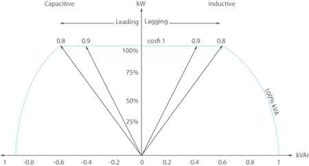
Power factor leading vs lagging describes whether current leads or lags voltage. A lagging power factor indicates inductive loads like motors. A leading power factor results from capacitive loads. Both affect energy efficiency, system stability, and power quality in electrical systems.
What is: "Power Factor Leading vs Lagging"?
Power factor leading vs lagging is an essential concept for any industrial electrician. This concept directly impacts the efficiency, safety, and cost-effectiveness of electrical systems in industrial settings.
✅ Indicates whether current leads or lags voltage in an AC circuit
✅ Lagging power factor arises from inductive loads (e.g., motors, transformers)
✅ Leading power factor comes from capacitive loads (e.g., capacitor banks, long cables)
By understanding the differences between leading and lagging PF, electricians can optimize energy delivery, minimize energy waste, and prevent costly equipment damage. Let's explore the key factors influencing PF, including reactive power (Q), apparent power, phase angle, and impedance. We can also explore the causes and effects of leading and lagging power factor, as well as strategies for PF correction. By mastering this knowledge, industrial electricians can ensure the reliable and efficient operation of critical electrical systems. To fully understand the relationship between voltage and current in AC circuits, see our guide on apparent power vs real power.
Power Quality Analysis Training
Request a Free Power Quality Training Quotation
A key player in this scenario is Q. Unlike real power, which performs the actual work, Q represents the energy stored and released by components like capacitors and inductors. This stored energy is essential for the operation of many devices but doesn't directly contribute to useful work. The interplay between real and Q determines the apparent power, which is the total power delivered to the circuit.
Electricity Today T&D Magazine Subscribe for FREE

- Timely insights from industry experts
- Practical solutions T&D engineers
- Free access to every issue
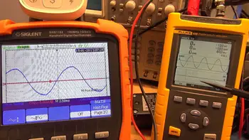
When the current leads the voltage, we have a leading PF, typically associated with capacitive loads. Capacitors store energy in an electric field, and this stored energy can influence the current waveform. Conversely, when the current lags behind the voltage, we encounter a lagging PF, commonly caused by inductive loads. Inductors, like motors and transformers, store energy in magnetic fields, affecting the current flow.
The phase angle, which is the angular difference between the voltage and current waveforms, provides a visual representation of this relationship. A larger phase angle indicates a greater disparity between voltage and current, resulting in a lower PF. This concept is effectively illustrated by the power triangle, a graphical tool that depicts the relationship between real, reactive, and apparent power.
To remember the relationship between leading and lagging power factors and the type of load, we can rely on the mnemonic "ELI the ICE man." ELI signifies that in an inductive load (L), the voltage (E) leads the current (I), resulting in a lagging PF. ICE, on the other hand, indicates that in a capacitive load (C), the current (I) leads the voltage (E), giving rise to a leading pPF. Lagging power factor is commonly caused by motors—learn more in our article on motor power factor and its impact on system performance.
Impedance, the total opposition to current flow in an AC circuit, also plays a role in determining the PF. Impedance encompasses both resistance and reactance, and the balance between these components influences the phase angle and, consequently, the PF.
However, a less-than-ideal PF, whether leading or lagging, can have undesirable consequences. It can lead to increased energy consumption, higher costs, and potential overloading of electrical systems. To address these issues, PF correction techniques are employed. Often, this involves adding capacitors to counteract the effects of inductive loads, bringing the PF closer to unity.
Another factor that can influence the PF is harmonic distortion. Harmonics are unwanted frequencies in the electrical system that can distort the current waveform and contribute to a lagging PF. Addressing harmonic distortion is crucial for effective PF correction. Discover the significance of power factor correction in maintaining system stability and preventing utility penalties.
Understanding the dynamics of power factor leading vs lagging is essential for ensuring the efficient and reliable operation of electrical systems. By recognizing the roles of Q, apparent power, phase angle, and impedance, and by employing appropriate PF correction strategies, we can optimize energy delivery and minimize energy waste. Discover how an automatic power factor controller dynamically adjusts leading or lagging conditions for improved efficiency.
Frequently Asked Questions
Why is managing both leading and lagging power factors important?
Managing both leading and lagging power factors is critical because a balanced PF (ideally close to 1.0) improves energy efficiency, reduces strain on equipment, and minimizes losses. An unmanaged lagging PF, often due to inductive loads, results in increased current demand, which can lead to heating and energy waste. Similarly, an unmanaged, leading PF, typically from capacitive loads, can cause voltage instability. Properly balanced PF correction helps ensure a stable, efficient, and cost-effective system.
How can leading and lagging power factors be corrected?
To correct a lagging PF caused by inductive loads, PF correction capacitors are often added to the system, as they provide leading reactive power to counterbalance the lagging effect. For a leading PF, inductive elements like reactors can be introduced to offset the capacitive influence. Additionally, APFC systems are often used to dynamically adjust for either leading or lagging power factors, ensuring balanced energy usage regardless of load changes.
Sign Up for Electricity Forum’s Power Quality Newsletter
Stay informed with our FREE Power Quality Newsletter — get the latest news, breakthrough technologies, and expert insights, delivered straight to your inbox.
What are the effects of a leading power factor on an electrical system?
A leading PF can result in overvoltage issues, especially in systems where capacitive loads dominate, as excess leading Q may cause voltage to increase beyond safe levels. This can lead to potential damage or maloperation of sensitive equipment, system instability, and inefficiency. While leading power factors are less common in typical industrial settings than lagging power factors, they must be carefully managed to avoid these issues, especially in transmission lines where capacitive effects are more pronounced.
How do utility companies view leading and lagging power factor?
Utility companies generally prefer a PF close to 1.0 because it indicates efficient use of energy. A significant deviation, whether lagging or leading, often leads to inefficiencies in the grid and may result in penalties for industrial or commercial customers. Utilities commonly penalize a lagging PF, as it is more prevalent with inductive loads; however, some utilities may also penalize a leading PF if it disrupts voltage stability or requires additional equipment to handle the excess capacitive energy. For a detailed explanation of the calculation process, visit our power factor formula page, which breaks down the key components.
In essence, power factor, which describes the relationship between voltage and current in AC circuits, is categorized as either leading or lagging. A leading PF, caused by capacitive loads, means the current peaks before the voltage, while a lagging PF, caused by inductive loads, means the current peaks after the voltage. This timing difference, represented by the phase angle, affects the efficiency with which energy is used. Understanding this relationship is crucial for industrial electricians to optimize energy delivery, reduce energy waste, and prevent equipment issues, ultimately contributing to safer and more cost-effective electrical systems.


