Power Factor Formula in AC Systems and Phase Angle
By William Conklin, Associate Editor
By William Conklin, Associate Editor
Our customized live online or in‑person group training can be delivered to your staff at your location.

Power factor formula is PF = kW ÷ kVA, or PF = cos θ in sinusoidal AC systems. The equation shows how real power, apparent power, reactive power, and phase angle influence current, loading, and correction decisions in AC equipment.
Power factor expresses the relationship between useful output and total electrical demand, but the engineering issue is not the ratio alone. The real question is what a low value says about phase shift, reactive loading, waveform condition, and whether the system is facing a simple correction issue or a more complex power quality problem.
In operating equipment, PF is not just a classroom ratio. A declining value means more current is required to deliver the same useful output, and that extra current affects feeders, transformers, voltage stability, spare capacity, and, in some facilities, utility penalty exposure.
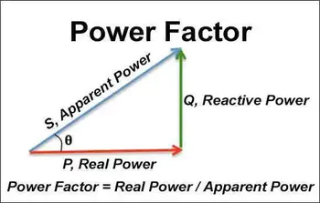
The standard power factor formula is PF = kW ÷ kVA. In sinusoidal AC systems, it is also written as PF = cos θ, where θ is the phase angle between voltage and current. Both forms describe the same relationship from different angles. Apparent Power is the total electrical demand seen by the source, while Apparent Power Formula explains how that total is derived mathematically.
Real power is the portion that performs useful work, such as motion, heat, or light. Apparent power is the total supplied power made up of real power and reactive power. Reactive power does not produce shaft output or heat on its own, but it still drives current and affects how AC systems behave. Reactive Power Formula helps separate that field-support component from the working portion of the load.
Think you know Power Quality? Take our quick, interactive quiz and test your knowledge in minutes.
In a clean sinusoidal system, the two expressions describe the same condition. One is written from measured power quantities and the other from waveform geometry. That is why How to Calculate Power Factor and Power Factor Calculation both matter. One emphasizes the arithmetic relationship, while the other emphasizes how measured values are interpreted in service.
If a three-phase load draws 300 kW and 346 kVA, the power factor is 300 ÷ 346, or about 0.87. That value does not automatically tell you what to fix, but it does tell you the system is drawing more current than a unity condition would require for the same useful output. On large equipment, that difference can alter transformer loading, conductor heating, and the margin available for expansion.
The power factor formula matters because current rises as PF falls for the same kW demand. That creates a cascading consequence. More current increases I²R heating; higher heating raises conductor and transformer stress; added stress reduces operating margin; and reduced margin narrows the room for new loads or abnormal conditions. That is why a low PF reading belongs in an operating decision, not just in a math exercise.
A poor value often leads people straight to correction, but that move comes with a trade-off. Power Factor Correction can reduce current and free up capacity, yet overly aggressive correction can create leading conditions at light loads or interact poorly with switching changes and capacitor steps. A site that targets 0.95 all day, regardless of load swing, may improve one billing metric while increasing instability elsewhere.
There is no universal action point that fits every facility. Some sites start paying attention below 0.95, others below 0.90, and some only when the value stays low during high-demand periods. The real threshold depends on the tariff, the load profile, the transformer headroom, and the persistence of the condition. A temporary dip during motor starting is not the same decision problem as an all-shift lagging condition on a heavily loaded bus.
The simple interpretation of the formula becomes less reliable when nonlinear loads distort the waveform. In that case, PF can look poor even when the issue is not just phase displacement. Harmonic-rich systems, variable frequency drives, and mixed electronic loads can make PF appear to be a simple capacitor problem when it is actually a distortion problem. Total Harmonic Distortion and Motor Power Factor become more useful when the number does not match the operating behavior seen on the floor.
A low PF result should change what the engineer checks next. It should trigger questions about load type, persistence, waveform shape, and where the extra current is injected into the system. A low PF value does not automatically mean the system needs capacitor correction. It may indicate normal inductive loading, a changing motor profile, poor operating timing, or waveform distortion that warrants deeper review before equipment is added. The formula is useful because it narrows the problem, not because it solves it on its own.
Download our FREE Electrical Training Catalog and explore a full range of expert-led electrical training courses.

Advantages To Instructor-Led Training – Instructor-Led Course, Customized Training, Multiple Locations, Economical, CEU Credits, Course Discounts.
Request For QuotationWhether you would prefer Live Online or In-Person instruction, our electrical training courses can be tailored to meet your company's specific requirements and delivered to your employees in one location or at various locations.