Power Factor Correction Sizing and Harmonic Risk Control
By John Houdek, Power Quality Editor
By John Houdek, Power Quality Editor

Our customized live online or in‑person group training can be delivered to your staff at your location.
Power factor correction governs reactive power flow, kVAR sizing, capacitor banks, detuning reactors, and exposure to harmonic distortion. Improper compensation can trigger resonance, transformer overheating, utility penalties, and voltage instability in industrial systems.
Industrial facilities do not install capacitor banks to improve textbook efficiency. They install them to control demand penalties, stabilize bus voltage under inductive load, and prevent excessive reactive current from consuming transformer capacity. The decision is not about improving the power factor. The decision is how far to implement power factor correction without destabilizing the system.
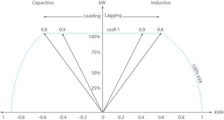
In motor-dominated plants, lagging power factor below 0.90 can trigger utility penalties or elevated kVA billing multipliers. Raising the power factor toward 0.95 or higher reduces reactive current and frees thermal margin in cables and transformers. However, pushing toward unity without evaluating harmonic conditions can introduce parallel resonance at characteristic harmonic frequencies.
Power factor correction, therefore, becomes a threshold discipline problem. It sits at the intersection of reactive power management and harmonic risk governance, not simple energy efficiency improvement.
Industrial billing models typically penalize facilities when power factor falls below a contractual threshold, commonly 0.90 or 0.95. The power factor correction target must therefore be defined relative to penalty avoidance and load variability, not theoretical unity. Correction strategy must align with the broader Power Factor control framework to avoid overcompensation and instability.
Within the broader discipline defined in Power Quality, reactive power management is only one boundary condition among voltage stability, harmonic distortion, and equipment tolerance limits.
Understanding the relationship between real, reactive, and apparent components requires a structured analysis of Apparent Power and the associated kVA loading limits of transformers and generators. When reactive current is reduced, available capacity increases without upgrading equipment.
Stay informed with our FREE Power Quality Newsletter — get the latest news, breakthrough technologies, and expert insights, delivered straight to your inbox.
Sizing begins with accurate load data and application of the Reactive Power Formula to determine required kVAR compensation at peak demand. Facilities commonly install power factor correction of 200-1500 kVAR per major bus section, depending on motor density and transformer rating. Undersizing leaves penalties in place. Oversizing introduces new instability.
This introduces the first deployment tradeoff: fixed capacitor banks offer simplicity and low capital cost, but staged systems controlled by an Automatic Power Factor Controller provide a dynamic response to fluctuating load. In plants with variable production cycles, fixed banks can overcorrect during light load, driving the system into a leading condition.
Industrial systems increasingly operate with variable frequency drives, rectifiers, and non linear loads that elevate current total harmonic distortion beyond 15 percent. Installing power factor correction capacitors into such environments without harmonic evaluation can shift system impedance and create parallel resonance near the 5th or 7th harmonic.
The interaction between compensation equipment and distortion levels is governed by the broader discipline of Power Quality and Harmonics. If voltage THD approaches 5 percent at the point of common coupling, detuning reactors become necessary to shift the resonant frequency away from dominant harmonics.
A common operational edge case occurs in facilities with high VFD concentration, where current THD ranges between 18 and 22 percent. Adding a non-detuned power factor correction capacitor bank can amplify harmonic voltages by more than 100 percent at the bus, doubling the RMS current in the capacitor elements and accelerating dielectric failure. What began as a penalty mitigation project becomes a reliability exposure.
Improperly staged power factor correction can trigger a cascading sequence. During peak load, additional kVAR steps are energized to maintain the target power factor. When production drops abruptly, those steps may remain engaged for a moment. The system shifts into leading power factor, increasing bus voltage. Elevated voltage interacts with harmonic components, increasing transformer heating and nuisance protective relay operation. A voltage excursion that appears minor at first can propagate into a plant-wide trip.
If restoration performance and uptime are board-level metrics, reactive power mismanagement is no longer an electrical detail. When a 2 MW production line trips because of resonance induced relay misoperation, the cost of improper kVAR sizing can exceed years of avoided penalty charges.
Power factor correction strategies must therefore integrate continuous verification through Power Quality Monitoring. Without permanent waveform capture and event logging, facilities cannot confirm whether resonance conditions or overvoltage episodes coincide with capacitor switching events.
Power factor values are not static. They fluctuate with motor loading, welding cycles, and seasonal process variation. Measurement resolution and averaging windows influence the reported power factor. Using a basic indicator rather than a Class A instrument can obscure short duration excursions that affect billing or stress equipment.
Accurate power factor correction assessment often requires a calibrated Power Quality Analyzer to capture waveform distortion, switching transients, and harmonic spectra. Without reliable data, kVAR sizing decisions rest on incomplete information, increasing the probability of overcorrection.
Calculations used to estimate compensation requirements should be validated against structured methods such as Power Factor Calculation. However, the calculation is only the starting boundary. The governing question remains whether the system impedance profile can tolerate the added capacitance.
Power factor correction capacitors degrade under thermal stress and harmonic loading. Elevated harmonic currents increase internal temperature and reduce service life. Periodic inspection, infrared scanning, and step verification are necessary to ensure the staged response remains aligned with evolving load conditions.
Facilities that expand motor capacity or add high frequency drives must reassess the correction design. A bank sized for a resistive-dominated load profile may become unstable as distortion increases. The correction boundary must evolve with the plant.
Download our FREE Electrical Training Catalog and explore a full range of expert-led electrical training courses.

Power factor correction is therefore not a one time installation decision. It is an ongoing governance function balancing penalty avoidance, harmonic risk, voltage stability, and equipment longevity.
Advantages To Instructor-Led Training – Instructor-Led Course, Customized Training, Multiple Locations, Economical, CEU Credits, Course Discounts.
Request For QuotationWhether you would prefer Live Online or In-Person instruction, our electrical training courses can be tailored to meet your company's specific requirements and delivered to your employees in one location or at various locations.