What is Reactive Power Explained
By Frank Baker, Associate Editor
By Frank Baker, Associate Editor
Our customized live online or in‑person group training can be delivered to your staff at your location.

Reactive power is the energy in AC systems that supports voltage and magnetic fields, enabling motors, transformers, and other inductive loads to operate. It does no real work, but it is essential for stable and efficient power distribution.
Reactive power is a fundamental part of AC electricity, yet it is often misunderstood. It is not wasted energy, and it is not a defect in a system. Instead, it is the energy that moves back and forth between a power source and a load to sustain magnetic and electric fields. Motors, transformers, HVAC equipment, and many industrial processes cannot operate without it. Understanding reactive power is essential because it affects current flow, voltage stability, system capacity, and utility billing. Understanding how these components interact helps explain why power factor may remain low even when the fundamental current appears well compensated.
Power Quality Analysis Training
Request a Free Power Quality Training Quotation
Every alternating current circuit produces a changing voltage and current. When an electrical device needs a magnetic field to operate, part of the current does not convert into mechanical work or heat. It is used to build and collapse that magnetic field each cycle. This circulating energy is reactive power. It appears naturally whenever inductance or capacitance is present. In practical terms, any industrial facility with motors, transformers, welders, compressors, or solenoids relies on reactive power every second of operation. Engineers analyzing reactive demand often start with a broader look at system performance, which is covered in our overview of what is power quality.
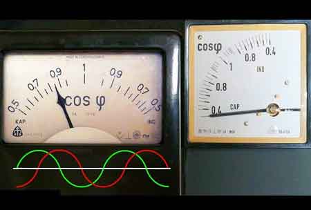
Inductive equipment resists rapid changes in current. When the voltage rises, the current cannot immediately follow, because magnetic fields must first establish themselves. This creates a time shift where the current lags behind the voltage. The greater the inductance, the larger the lag. This lagging relationship is the cause of reactive power. Motors, chokes, magnetic ballasts, and welding transformers all produce this effect. Although it does not perform work, the system must continuously supply this energy.
Download our FREE Electrical Training Catalog and explore a full range of expert-led electrical training courses.

Reactive power behaviour can be understood in terms of inductive and capacitive reactance. Inductive reactance increases with frequency, causing the current to lag behind the voltage. Capacitive reactance decreases as frequency increases, causing current to lead. Real systems often contain both types of reactance, and the net effect determines the amount of reactive power flowing at any given moment. These concepts form the engineering basis for power factor correction and system modelling. When reactive power causes excessive current and flicker issues, maintenance teams often troubleshoot using techniques described in our guide to power quality and harmonics.
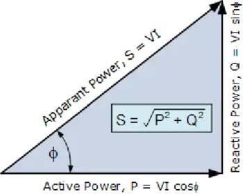
Reactive power can only be understood in relation to real power and apparent power. The power triangle is a simple way to visualize this relationship. Real power (kW) performs useful work. Reactive power (kVAR) supports the fields that allow work to happen. Apparent power (kVA) is the vector sum of both. The angle between real and apparent power defines the power factor. As reactive demand increases, the angle widens, current rises, and efficiency drops. Improving the power factor reduces unnecessary current and frees capacity.
The classic power triangle explains how different forms of power relate to one another. Real power (kW) performs actual work. Reactive power (kVAR) maintains magnetic and electric fields. Apparent power (kVA) represents the vector sum of both. The angle between the real and apparent powers determines the power factor. When reactive power is excessive, the system must carry more current to deliver the same amount of real work, increasing losses and reducing available capacity. When reactive power is well managed, operating conditions improve, heating is reduced, and voltage stability increases. To better understand current flow disruptions in AC systems, compare real vs reactive power and how each influences overall electrical safety.
Utilities measure reactive power in kilovolt-amperes reactive (kVAR). Modern metering systems track kW, kVA, and kVAR to determine the power factor of a customer’s load. A low power factor indicates that more current is flowing than is necessary to perform the real work. This additional current strains transformers, conductors, and switchgear. Many utilities apply penalties when reactive demand is too high because it forces the electrical network to operate less efficiently.
Reactive power directly affects voltage levels in transmission lines and feeders. High lagging reactive demand pulls voltage down, while excessive leading reactive power can push voltage above acceptable limits. Utilities use tap-changing transformers, voltage regulators, capacitor bank switching, and synchronous condensers to maintain proper voltage profiles. Because reactive power does not travel efficiently over long distances, it must be supplied close to where it is consumed.
Capacitor banks generate leading reactive power that offsets the lagging reactive power drawn by inductive equipment. Understanding how inductive and capacitive effects shape reactive current is easier when you compare a capacitive load with inductive equipment. When installed correctly, they reduce the reactive burden on the supply, lower system current, improve voltage stability, and help customers avoid utility penalties. Automatic controllers can add or remove capacitor stages as loads vary, maintaining an optimal power factor throughout the day. Facilities working to improve poor power factor often rely on technologies described in our guide to automatic power factor controllers.
More complex facilities may use additional correction tools. Synchronous condensers can dynamically generate or absorb reactive power. Active harmonic filters address both reactive demand and harmonic distortion. STATCOM systems provide rapid reactive support for fluctuating or sensitive loads. These technologies enable fine control of voltage and power factor in systems operating under rapidly changing electrical conditions.
Stay informed with our FREE Power Quality Newsletter — get the latest news, breakthrough technologies, and expert insights, delivered straight to your inbox.
Engineers evaluate reactive power using RMS voltage and current because these values reflect the true heating and loading effects on equipment. RMS measurements account for waveform shape, frequency, phase angle, and possible distortions. Reactive effects appear in every AC sine wave and become especially important when analyzing the performance of motors, drives, or nonlinear loads.
Motors require reactive power to establish torque-producing magnetic fields. Transformers generate reactive power as they transfer energy and regulate voltage. Welders and arc furnaces create rapidly changing inductive conditions. HVAC compressors and fans draw fluctuating reactive loads that vary with demand. These examples show that reactive power is not optional. It is woven into the operation of almost every modern electrical system. Evaluating reactive demand in real time requires accurate monitoring tools, such as those outlined on our page about the power quality analyzer.
When reactive demand becomes too high, current throughout the system increases. Higher current causes greater heating in cables and equipment, reduces available capacity, and increases energy losses. Voltage may sag under heavy load, motors may run hotter, and protective devices may operate closer to their ratings. While reactive power is essential, too much of it creates avoidable operational and financial problems.
Digital meters, power quality analyzers, and SCADA systems give facility operators real-time insight into reactive power flows. These tools measure phase angle, harmonics, and kVAR demand. Continuous monitoring helps detect inefficiencies, identify equipment issues, and verify that corrective systems, such as capacitor banks or filters, are functioning properly.
Reactive power sustains the magnetic and electric fields required by motors, transformers, and many other types of equipment.
It is not wasted, but unmanaged reactive demand increases system current and reduces efficiency.
It cannot be eliminated because inductive loads require it. It can only be supplied, balanced, or compensated.
Reactive power is essential to the operation, stability, and efficiency of AC power systems. When properly understood and managed, electrical networks operate more reliably, with lower losses and lower costs. When it is ignored, systems run hotter, equipment ages faster, and utilities impose higher charges. Effective control of reactive power benefits both facilities and the broader power grid.
Explore 50+ live, expert-led electrical training courses –