Power Factor Control and Reactive Power Governance
By John Houdek, Power Quality Editor
By John Houdek, Power Quality Editor
Our customized live online or in‑person group training can be delivered to your staff at your location.

Power factor governs whether electrical systems operate within thermal, economic, and stability limits. In industrial environments, it determines how efficiently real power is converted into productive work relative to the apparent power drawn from the supply.
Power factor equals real power divided by apparent power in an alternating current system and is commonly expressed as cos phi. This relationship defines how much current must flow to deliver a given amount of usable energy.
When the power factor declines, the current increases for the same real power output. Elevated current does not affect billing alone. It stresses conductors, transformers, and protection devices. Reactive power flow alters voltage profiles and complicates coordination.
In large industrial systems, power factor performance directly defines thermal loading margin, tariff exposure, and voltage regulation stability. When the correction strategy is poorly defined, capacitor switching, harmonic interaction, and voltage instability can compound into cascading system stress.
Power factor is the ratio of real power to apparent power and functions as a measurable boundary within broader Power Quality governance. It is commonly represented as cos (φ), reflecting the phase angle between voltage and current in alternating current systems.
In balanced three phase networks, the relationship between kW, kVAR, and kVA defines how much current must be delivered to sustain mechanical load. A facility drawing 1,000 kW at 0.80 power factor requires 1,250 kVA. Improving that value to 0.95 reduces the required apparent power to approximately 1,053 kVA. The current reduction approaches 16 percent. That reduction directly influences conductor heating and transformer loading margin.
The distinction between resistive and inductive behavior becomes visible when comparing a Resistive Load to a Capacitive Load. Purely resistive systems maintain a unity power factor. Inductive motor circuits and transformers introduce reactive demand, shifting the phase angle and lowering cos phi.

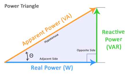
The mathematical relationship is governed by the power triangle. Real power performs useful work. Reactive power sustains magnetic fields. Apparent power is the vector sum.
Industrial engineers frequently reference Apparent Power and apply the Apparent Power Formula when evaluating transformer and generator capacity. Misinterpreting this relationship can lead to undersized equipment or inflated demand charges.
A threshold discipline issue arises when facilities assume that deviations below 0.90 are tolerable. Utility power factor tariffs often apply penalty multipliers below defined limits. Once crossed, incremental reactive demand produces a disproportionate financial impact. The operational decision is therefore a boundary determination, not a gradual adjustment.
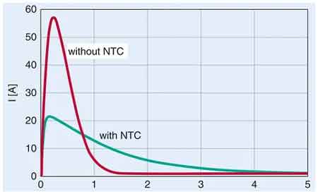
Improving power factor typically involves capacitor banks or staged control systems, such as an Automatic Power Factor Controller. The tradeoff lies between centralized bulk correction and distributed point of load correction.
Centralized correction simplifies maintenance but may not address localized voltage drop. Distributed correction improves feeder balance but increases switching complexity and the risk of harmonic interactions.
Overcorrection introduces leading power factor conditions. In lightly loaded systems, this can elevate voltage and interfere with voltage regulation schemes. The correction decision, therefore, requires coordination with the Power Factor Correction strategy and harmonic evaluation.
Consider a manufacturing facility operating multiple large induction motors at a power factor of 0.78. Without correction, current increases across feeder conductors. Elevated thermal stress reduces transformer life expectancy. Protection settings tuned to nominal current may misinterpret elevated reactive current as an overload. Nuisance tripping interrupts production.
Once reactive demand grows beyond transformer capacity margin, voltage sag susceptibility increases. Equipment shutdown then cascades across process lines. What begins as reactive inefficiency evolves into operational downtime and capital replacement exposure.
If production continuity is a board level metric, unmanaged power factor becomes an executive risk variable.
Power factor limits are rarely determined solely by physics. They are typically defined by tariff language, internal engineering standards, or transformer thermal margins. The decision is not whether the power factor should be improved. The decision is where the lower acceptable boundary should be set.
Many utilities impose penalties for power factors below 0.90 or 0.95. Operating slightly above those thresholds may satisfy billing compliance while still increasing conductor losses and reducing transformer life expectancy. A facility running at 0.91 power factor may technically avoid penalty multipliers, yet still operate with compressed thermal reserve.
This creates a threshold discipline issue. If the power factor is allowed to drift until it reaches the penalty trigger, correction becomes reactive rather than controlled. Incremental decline increases reactive current, elevates I-squared R losses, and reduces voltage stability margin across feeders.
Low power factor conditions increase current stress, magnify conductor losses, and accelerate transformer heating under sustained load. High power factor performance reduces apparent power demand, stabilizes feeder loading, and extends thermal operating margin.
Industrial power factor performance must therefore be measured against internal engineering targets, not tariff minimums. A power factor improvement strategy that focuses only on avoiding penalties can leave reactive inefficiencies embedded within the distribution system.
Power factor, therefore, requires internal governance targets that are tighter than external compliance thresholds. Setting a 0.97 internal control point instead of 0.90 changes how correction equipment stages, how switching is scheduled, and how reactive demand is monitored.
Think you know Power Quality? Take our quick, interactive quiz and test your knowledge in minutes.
The unresolved boundary is this: how high should the target power factor be before diminishing returns and overcorrection risk outweigh efficiency gains? That decision depends on load variability, harmonic presence, and system impedance.
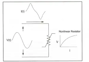
Distributed energy resources and variable speed drives introduce distortion, complicating phase-angle measurement. In distorted waveforms, a simple cos phi interpretation can misrepresent the true power factor. Engineers must distinguish between displacement power factor and total power factor when harmonics are present.
Accurate diagnosis often requires a Class A instrument, such as a Power Quality Analyzer, operating under structured logging intervals consistent with Power Quality Monitoring. Without reliable data resolution, correction strategies risk misalignment.
A quantified authority signal illustrates deployment scale. Large industrial campuses often manage tens of megavolt amperes across multiple substations. A 5 percent improvement in power factor across a 20 MVA system reduces the reactive burden by approximately 1 MVA. That reduction directly influences transformer thermal reserve and upstream capacity allocation.
An accurate correction strategy depends on a structured data review supported by formal Power Quality Analysis, especially when harmonic distortion and phase angle shift coexist.
Power factor cannot be isolated from broader power quality considerations. Harmonic distortion, voltage imbalance, and switching transients interact with correction equipment.
Facilities performing formal Power Factor Calculation should integrate harmonic screening before deploying correction capacitors. Threshold discipline must define acceptable limits for both displacement and distortion driven conditions.
The unresolved boundary is this: at what point does incremental correction introduce more system complexity than operational benefit? That decision cannot be standardized across the board. It must be evaluated against system impedance, load variability, and regulatory exposure.
Power factor affects transformer loading, conductor heating, and tariff exposure simultaneously. Power factor affects conductor heating. Power factor affects tariff exposure.
In practical terms, power factor determines how much apparent power must be supplied to deliver usable real power. When the power factor deteriorates, electrical capacity is consumed without productive output. When the power factor improves, the current declines, and the system margin expands.
Power factor therefore functions as both an electrical efficiency metric and a system governance variable. Sustained power factor control is not optional in high-load environments. It determines how much current must be delivered, how much heat must be dissipated, and how much reactive demand must be compensated. It simultaneously influences equipment stress, billing exposure, and voltage stability. Treating it as a static ratio obscures its operational leverage.
Explore 50+ live, expert-led electrical training courses –